GWPR-AF-S Series Arc-Flash Sensors
- The GWPR-AF-S series comprises fiber-optic arc-flash sensors for detecting internal arc faults in switchgear. The sensors are designed for use with the GWPR220-AF Feeder Arc-Flash Protection Relay and the GWPR350-AF Busbar Arc-Flash Protection Relay.
- When an internal arc fault occurs, the sensors detect the resulting optical radiation and transmit an optical signal to the connected protection relay through an optical-fiber link. The relay evaluates the optical signal together with the configured electrical permissive criteria and operating logic, then initiates an alarm or trip output as required.
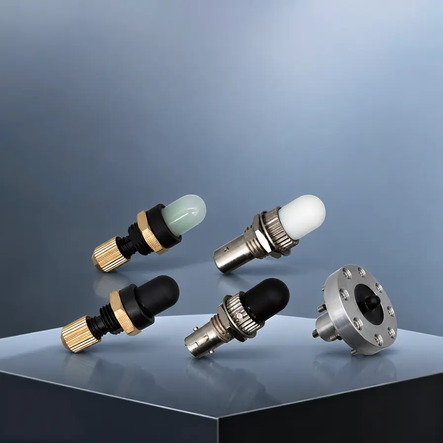
- The series provides different spectral responses, self-test functions, fields of view, sensing methods and mounting arrangements. Available configurations include broad-spectrum UV–visible sensors, UV sensors, self-test sensors, lens-type sensors, flange-mounted sensors, wide-angle point sensors and light-sensitive optical-fiber sensors.




Product Description
Operating Principle
- During an internal arc fault, optical radiation within the affected switchgear compartment increases rapidly. A GWPR-AF-S sensor detects this radiation and transmits an optical signal to the connected arc-flash protection relay.
- The sensor performs arc-flash detection and optical-signal transmission. The arc-flash pickup threshold, electrical permissive criteria, output logic and operating delays are configured in the protection relay.
- The total fault-clearing time depends on the sensor response time, relay processing time, trip-output operating time, external trip-circuit delay and circuit-breaker opening time.
Protection Functions and Operating Logic
The optical signal supplied by a GWPR-AF-S sensor can be used to form protection criteria, initiate alarms, and support tripping and interlocking logic.
Protection criteria:
- Arc-flash-only tripping criterion.
- Arc-flash and overcurrent dual criterion.
- Arc-flash and residual-voltage dual criterion.
- Arc-flash, overcurrent and residual-voltage combined criterion.
Alarm function:
- Arc-flash alarm without a trip output.
Selective tripping and interlocking logic:
- Zone-selective tripping.
- Upstream and downstream interlocking.
Tripping based solely on the arc-flash criterion enables fast operation but requires careful control of external light sources. Combining the optical signal with an electrical permissive criterion, such as overcurrent or residual voltage, reduces the risk of unwanted operation while maintaining fast fault clearance.
The final operating criteria, pickup thresholds, operating times and output configuration must be determined according to the protection coordination study, switchgear design and site operating requirements.
Sensor Types
Broad-Spectrum UV–Visible Sensors
- Broad-spectrum models have a spectral response range of 200–700 nm. Because this range is not exclusively within the visible spectrum, these products are described as broad-spectrum UV–visible sensors rather than visible-light-only sensors.
- These models are suitable for applications requiring a broad optical response and conventional point detection. Their installation locations should be selected carefully to minimise exposure to unrelated external light sources.
Ultraviolet Sensors
- UV models have a spectral response range of 280–400 nm. Their spectral selectivity provides improved visible-light rejection in switchgear environments where inspection lamps, ambient lighting or other visible-light sources may be present.
- The suitability of a UV sensor should be evaluated according to the expected arc spectrum, switchgear construction, sensor location and possible external UV sources.
Self-Test Sensors
- Optical-path supervision refers to continuous monitoring of the optical link, while self-testing refers to an active test process used to verify that the sensor and optical path remain functional.
- When used with a compatible protection relay, self-test models support supervision of the sensor and optical path. Depending on the relay configuration, the system can detect fiber breakage, excessive optical attenuation and loss of the self-test signal.
- The ST suffix in these model designations means Self-Test. It does not indicate an ST-type fiber-optic connector unless this is specifically stated in the product datasheet.
Light-Sensitive Optical-Fiber Sensors
- Light-sensitive optical-fiber sensors provide distributed optical coverage along the sensing fiber. They are suitable for elongated compartments or protected areas where a single point sensor may not provide sufficient coverage.
- The sensing fiber must be installed in accordance with its specified minimum bend radius and mechanical installation requirements. Sharp bends, crushing, excessive tensile force and obstruction of the light-sensitive section should be avoided.
Coordination with GWPR Arc-Flash Protection Relays
The GWPR-AF-S series is designed for coordinated use with the following protection relays:
- The GWPR220-AF is intended for feeder compartments, cable compartments and other feeder-related protection zones.
- The GWPR350-AF supports multi-zone busbar and switchgear applications requiring multiple sensor channels, sensor-channel assignment, output-matrix configuration, zone-selective tripping and interlocking logic.
- The number of supported sensor channels, channel assignments and available protection functions must be confirmed against the selected relay model and project-specific configuration.
Zone-Based Protection
- Each sensor channel can be assigned to a defined protection zone. Based on the sensor channel that has operated, its assigned protection zone, the satisfied electrical permissive criteria and the configured output matrix, the relay can implement zone-selective tripping, bus-section isolation, and upstream and downstream interlocking.
- The required number of sensors and relay channels should be determined according to the protection-zone arrangement and switchgear construction, not solely according to the number of switchgear panels.
3. Product Selection
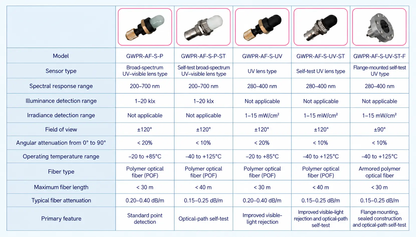
3.1 Lens-Type Arc-Flash Sensors
3.2 Wide-Angle Arc-Flash Sensors
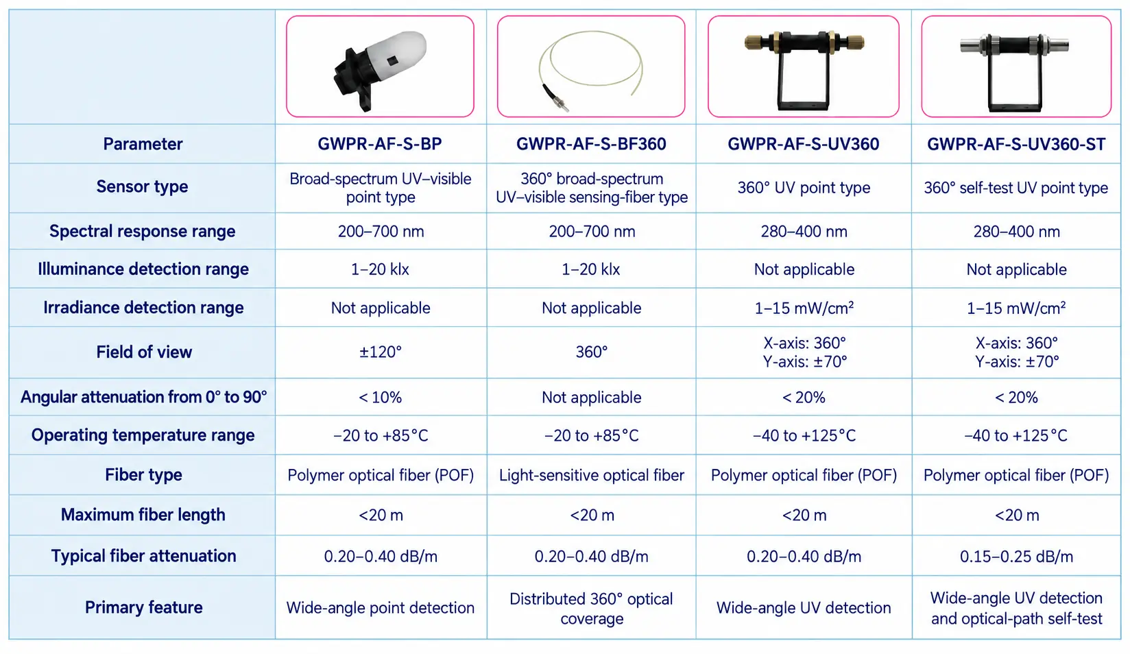
Note: This group does not consist exclusively of self-test sensors. Only the GWPR-AF-S-UV360-ST carries the ST suffix and is identified as a self-test model.
3.3 Model Designation
The model designations are defined as follows:
- GWPR identifies the GoWatron protection product family.
- AF means Arc Flash.
- S means Sensor.
- P means Point-Type.
- ST means Self-Test.
- UV means Ultraviolet.
- F means Flange-Mounted.
- BP means Broad-Spectrum Point.
- BF360 means Broad-Spectrum Sensing Fiber with 360° coverage.
- UV360 means Ultraviolet Detection with 360° horizontal coverage.
The ST suffix is separated by a hyphen throughout the series to distinguish the self-test function clearly from the basic sensor type. Examples include GWPR-AF-S-P-ST, GWPR-AF-S-UV-ST and GWPR-AF-S-UV360-ST.
Product model designations are assigned by the manufacturer. IEC and ANSI standards do not prescribe a universal model-naming system for arc-flash sensors.
3.4 Selection Guidance
- Standard point detection: The GWPR-AF-S-P and GWPR-AF-S-BP are suitable for applications requiring broad-spectrum UV–visible response and point-type optical detection.
- Visible-light rejection: The GWPR-AF-S-UV and GWPR-AF-S-UV360 are suitable for applications requiring selective UV response and improved rejection of visible-light interference.
- Optical-path supervision: The GWPR-AF-S-P-ST, GWPR-AF-S-UV-ST, GWPR-AF-S-UV-ST-F and GWPR-AF-S-UV360-ST may be used with compatible protection relays where optical-path supervision and self-test functions are required.
- Distributed optical coverage: The GWPR-AF-S-BF360 uses a light-sensitive optical fiber to provide distributed coverage along an elongated protection area.
- Flange-mounted installation: The GWPR-AF-S-UV-ST-F provides flange mounting, sealed construction and armored optical-fiber transmission for applications requiring through-panel installation.
- Final model selection should be based on the protected compartment, expected arc spectrum, field of view, installation arrangement, environmental conditions, required fiber length and protection-relay compatibility.
4. Product Advantages
- Optical Detection and Fiber-Optic Transmission: The sensors detect arc-flash radiation optically and transmit the resulting signal through optical fiber. The fiber-optic link does not require electrical signal amplification inside the switchgear and is inherently immune to electromagnetic interference.
- Fast Fault Detection: Direct optical detection supports rapid recognition of internal arc faults. The total fault-clearing time also depends on relay processing, trip-output operation, the external trip circuit and circuit-breaker opening time.
- Multiple Spectral Options: Broad-spectrum UV–visible and selective UV models are available for different optical environments. The appropriate spectral response can be selected according to the expected arc radiation and potential external light sources.
- Flexible Installation: Lens-type sensors, wide-angle sensors, flange-mounted sensors and light-sensitive optical-fiber sensors are available for different switchgear layouts, compartment dimensions and installation requirements.
- Zone-Based Protection: Individual sensor channels can be assigned to specific protection zones. When coordinated with the relay output matrix, this arrangement supports selective isolation of the affected zone and limits unnecessary interruption of unaffected circuits.
- Optical-Path Supervision: When used with a compatible relay, self-test models support supervision of the sensor and optical path, helping identify fiber breakage, excessive optical attenuation and loss of the self-test signal.
- Combined Protection Criteria: The optical signal can be combined with overcurrent, residual voltage or other electrical permissive criteria to balance fast fault clearance with security against unwanted operation.
5. Applications
- Medium-Voltage Switchgear: The sensors can be installed in incomer panels, feeder panels, bus-coupler panels, bus-section panels and voltage-transformer panels, including circuit-breaker, busbar and cable compartments.
- Low-Voltage Switchgear Assemblies: Typical applications include power distribution boards, withdrawable switchgear assemblies, feeder panels and motor control centers.
- Substations: The series can be applied in utility, industrial and commercial substations where rapid detection of internal arc faults is required.
- Industrial Power Systems: Applicable facilities include petrochemical plants, steelworks, mines, cement plants, manufacturing plants and other sites with critical electrical distribution systems.
- Renewable-Energy and Energy-Storage Systems: Applications include AC collector circuits, PV DC combiner circuits, feeder panels, distribution boards and substation switchgear in photovoltaic plants, wind farms and battery energy storage systems.
- Data Centers and Transportation Infrastructure: The sensors may be used in data centers, communication facilities, airports, urban rail and railway facilities, and other installations requiring high power-supply continuity.
- The quantity and location of sensors should be determined according to the switchgear compartments, possible arc-fault locations, required field of view, permitted fiber length and protection-zone arrangement. Sensor sightlines should not be obstructed, and optical fibers should be protected against excessive bending, crushing and mechanical damage.
- During commissioning, the sensor-to-channel mapping, optical-path condition, self-test alarms, arc-flash pickup threshold, electrical permissive criteria, trip outputs, interlocking logic and circuit-breaker trip circuit should be verified in accordance with the approved commissioning procedure.


