How to Select an Anti-Islanding Protection Relay for Solar PV Systems
- As solar photovoltaic (PV) installations continue to expand worldwide, reliable grid interconnection protection has become increasingly important. Anti-islanding protection is one of the key protection requirements for grid-connected PV systems.
- Selecting the right anti-islanding protection relay requires more than matching a relay to the PV system voltage. Engineers should also consider the required protection functions, applicable grid code, CT/VT configuration, communication protocols, SCADA integration, and overall grid interconnection protection scheme.
- This guide explains the operating principle, key selection factors, and recommended GoWatron anti-islanding protection relays for solar PV grid connection applications from 400 V to 132 kV.
1. What Is Islanding in a Solar PV System?
- Islanding occurs when a section of an electrical network becomes disconnected from the utility grid but continues to be energised by local photovoltaic generation.
- This condition may occur following utility-side faults, network outages, or switching operations if the PV generation is not properly disconnected from the isolated network.
Unintentional islanding can result in:
- Safety hazards for utility maintenance personnel
- Abnormal voltage and frequency conditions
- Damage to photovoltaic and customer equipment
- Interference with automatic reclosing and reclosing coordination
- Energisation of a network section expected to be de-energised
- Non-compliance with utility grid connection requirements
An anti-islanding protection relay monitors electrical conditions at the grid connection point and initiates disconnection of the PV generation when an islanding condition is detected.
2. Anti-Islanding Protection Principle
- An anti-islanding protection relay continuously monitors electrical quantities at the Point of Common Coupling (PCC), typically including voltage, frequency, rate of change of frequency, current, and power flow.
- When the measured quantities exceed the configured thresholds and satisfy the corresponding protection logic, the relay issues a trip command to the grid interconnection circuit breaker, separating the PV system from the utility network.
- In practical PV grid connection systems, several protection criteria are normally coordinated rather than relying on a single detection method.
2.1 Typical Anti-Islanding Protection Functions
- (ANSI 27) Undervoltage Protection
Detects voltage falling below the configured threshold following grid disturbances or loss of utility supply. - (ANSI 59) Overvoltage Protection
Detects voltage exceeding the configured threshold following grid disturbances or an imbalance between local generation and load. - (ANSI 81U) Underfrequency Protection
Detects system frequency falling below the configured threshold. - (ANSI 81O) Overfrequency Protection
Detects system frequency rising above the configured threshold. - (ANSI 81R) ROCOF Protection
Rate of Change of Frequency (ROCOF) protection monitors the rate at which system frequency changes (df/dt).
A rapid change in frequency can indicate grid separation, making ROCOF an important criterion in many anti-islanding protection schemes.
ROCOF pickup values and operating delays should be selected according to the applicable grid code, utility requirements, and system study. - (ANSI 32R) Reverse Power Protection
Reverse power protection monitors active power flow in the reverse direction and operates when the configured reverse-power criteria are satisfied.
Its application depends on the grid connection arrangement and project protection philosophy.
2.2 Passive and Active Anti-Islanding Detection
Anti-islanding protection may involve both passive and active detection methods.
Passive Anti-Islanding Detection
Passive detection monitors naturally occurring electrical quantities without deliberately disturbing the power system.
Typical quantities include:
- Voltage
- Frequency
- ROCOF
- Current
- Active power
- Power-flow direction
An external anti-islanding protection relay primarily uses these electrical quantities to identify abnormal grid conditions and initiate disconnection.
Active Anti-Islanding Detection
- Active anti-islanding detection is typically implemented within the grid-connected inverter.
- Depending on the inverter design and applicable grid connection requirements, the inverter may introduce a controlled perturbation and monitor the resulting electrical response to determine whether the utility grid remains connected.
Coordination of Active and Passive Detection
The two approaches can be complementary.
- Inverter-based active anti-islanding detection operates within the inverter control system, while an external anti-islanding protection relay can provide independent monitoring and tripping at the PCC or grid interconnection point.
- Whether both methods are required depends on the applicable grid code, utility requirements, inverter certification, plant capacity, voltage level, and overall protection philosophy.
3. Key Factors for Anti-Islanding Protection Relay Selection
3.1 Grid Connection Voltage
Grid connection voltage is one of the primary considerations when selecting an anti-islanding protection relay.
| Grid Connection Voltage | Recommended Relay | Typical Application |
| 400 V | GWPR100-AIP | Low-voltage distributed and rooftop PV |
| 11 kV / 22 kV | GWPR200-AIP | Medium-voltage distributed PV |
| 33 kV / 66 kV / 132 kV | GWPR300-AIP | Utility-scale PV and renewable energy substations |
Voltage level should be used as an initial selection reference rather than the sole selection criterion.
Final selection should also consider:
- PV plant capacity
- CT and VT configuration
- Required protection functions
- Applicable grid code
- Utility protection requirements
- Communication architecture
- SCADA/SAS integration
- Required digital inputs and outputs
- Installation method
3.2 Required Protection Functions
Typical anti-islanding protection functions include:
- (ANSI 27) Undervoltage Protection
- (ANSI 59) Overvoltage Protection
- (ANSI 81U) Underfrequency Protection
- (ANSI 81O) Overfrequency Protection
- (ANSI 81R) ROCOF Protection
- (ANSI 32R) Reverse Power Protection
Depending on the relay model and project requirements, additional protection and supervision functions may include:
- (ANSI 50/51) Overcurrent Protection
- (ANSI 67) Directional Overcurrent Protection
- (ANSI 51N) Zero-Sequence Overcurrent Protection
- (ANSI 59N) Zero-Sequence Overvoltage Protection
- VT Circuit Failure Detection
- Harmonic Detection
- External Trip / Intertrip
- Automatic Grid Reconnection
- Project-Specific Trip and Interlocking Logic
The exact function set varies between relay models. Final relay selection should therefore be based on the actual product specification and project requirements.
Functions such as VT Circuit Failure Detection, Harmonic Detection, External Trip / Intertrip, and Automatic Grid Reconnection are intentionally not assigned ANSI device numbers here unless the implemented function corresponds explicitly to a standard ANSI/IEEE device function.
3.3 Communication and SCADA Integration
For medium-voltage and utility-scale PV projects, anti-islanding protection relays are commonly integrated into plant SCADA or
substation automation systems.
Three communication concepts should be distinguished:
Communication Interface
Physical communication hardware, such as Ethernet or RS-485.
Communication Protocol
The data communication protocol, such as Modbus RTU, IEC 60870-5-103, IEC 60870-5-104, or IEC 61850.
Communication Management Device
A separate system-level device used for communication aggregation, protocol conversion, data forwarding, or integration with higher-level systems.
For the GoWatron anti-islanding protection relay range covered in this guide:
- GWPR100-AIP: RS-485 / Modbus RTU
- GWPR200-AIP: Ethernet / IEC 60870-5-103 over Ethernet; RS-485 / Modbus RTU
- GWPR300-AIP: Ethernet / IEC 60870-5-104; RS-485 / Modbus RTU; optional IEC 61850
The required interfaces and communication protocols should be selected according to the project SCADA/SAS architecture rather than voltage level alone.
3.4 Event and Disturbance Recording
- Event Recording
- Sequence of Events (SOE)
- Disturbance Recording
- Fault Waveform Recording
- IRIG-B Time Synchronisation
- SNTP Time Synchronisation
4. Recommended Anti Islanding Protection Relays
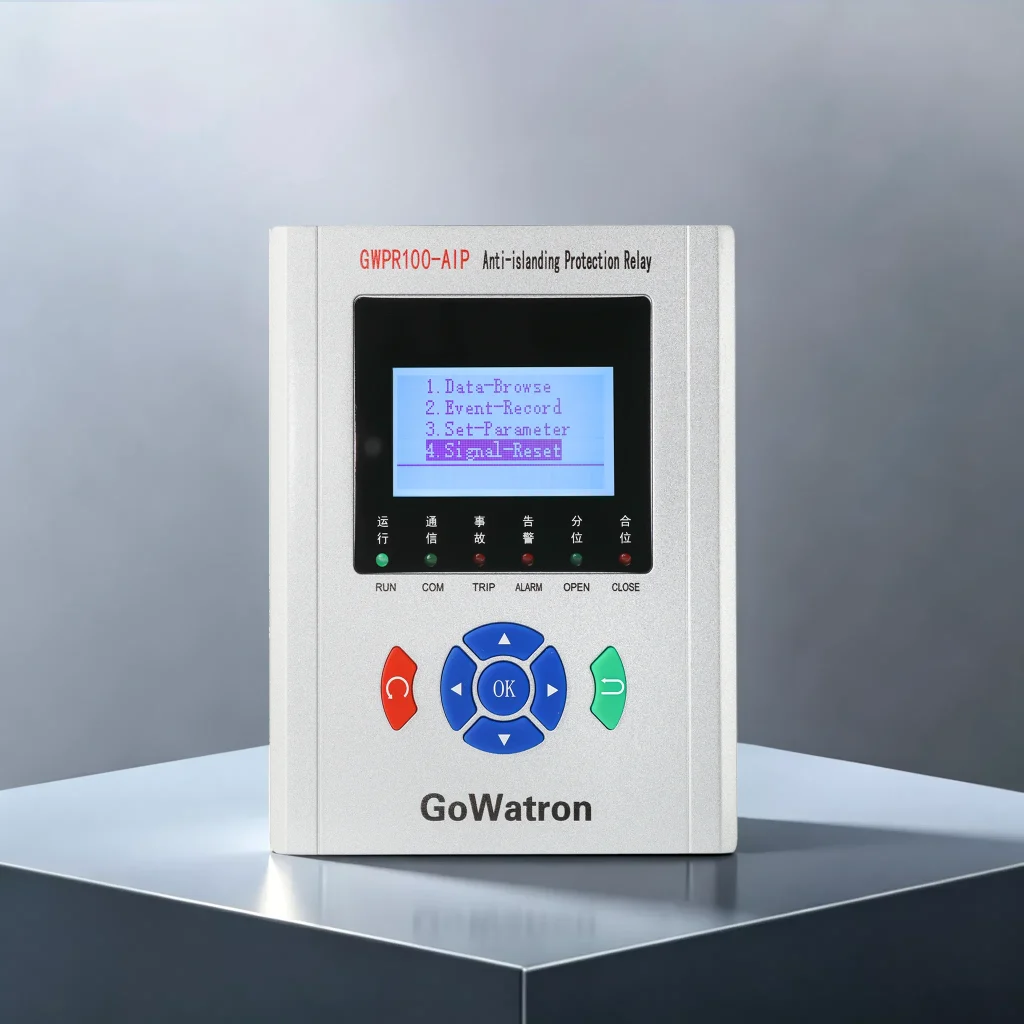
4.1 GWPR100-AIP Low Voltage Anti Islanding Protection Relay
The GWPR100-AIP Low Voltage Anti Islanding Protection Relay is designed for 400 V distributed photovoltaic grid connection applications.
Typical Applications
- 400 V Distributed PV Systems
- Commercial Rooftop PV
- Industrial Rooftop PV
- Low Voltage Distributed Generation
- PV Grid Connection Cabinets
Key Features
- Anti Islanding Protection
- (ANSI 27/59) Multi stage Voltage Protection
- (ANSI 81U/81O) Multi stage Frequency Protection
- (ANSI 81R) ROCOF Protection
- (ANSI 32R) Reverse Power Protection
- (ANSI 50/51) Multi stage Overcurrent Protection
- (ANSI 51N) Zero Sequence Overcurrent Protection
- External Trip / Intertrip
- Event Recording
- RS 485 Communication Interface
- Modbus RTU Communication Protocol
The GWPR100-AIP provides a compact protection, measurement, communication, and event recording solution for low voltage PV grid connection applications.
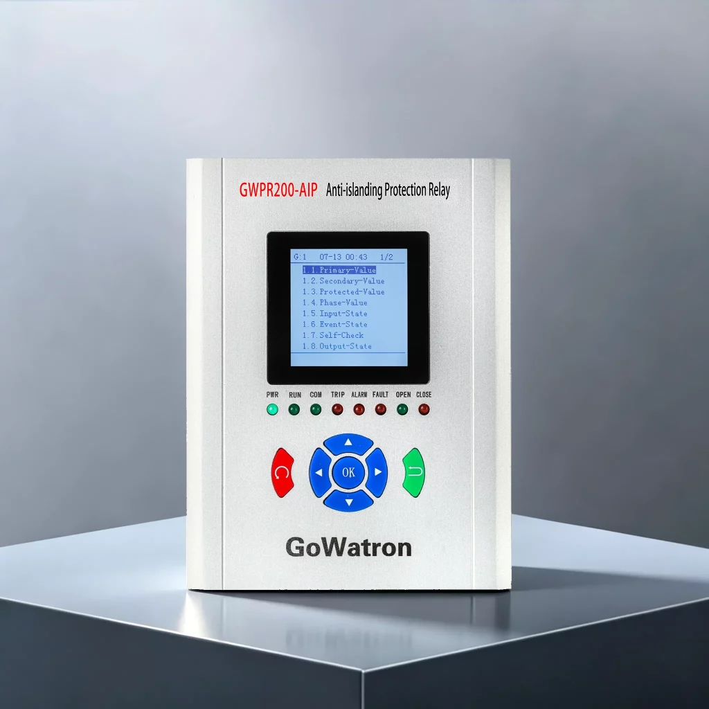
4.2 GWPR200-AIP Anti Islanding Protection Relay
The GWPR200-AIP Anti Islanding Protection Relay is designed for 11 kV and 22 kV distributed photovoltaic grid connection applications.
Typical Applications
- 11 kV PV Grid Connection
- 22 kV PV Grid Connection
- Commercial and Industrial PV Projects
- Medium Voltage Distributed Generation
- Medium Scale Solar Projects
Key Features
- Anti Islanding Protection
- (ANSI 27/59) Multi stage Voltage Protection
- (ANSI 81U/81O) Multi stage Frequency Protection
- (ANSI 81R) ROCOF Protection
- (ANSI 32R) Reverse Power Protection
- (ANSI 50/51) Overcurrent Protection
- (ANSI 51N) Zero Sequence Overcurrent Protection
- VT Circuit Failure Detection
- Harmonic Detection
- External Trip / Intertrip
- Automatic Grid Reconnection
- Event Recording
- Ethernet and RS 485 Communication Interfaces
- IEC 60870 5 103 over Ethernet
- Modbus RTU Communication Protocol
- SNTP and IRIG B Time Synchronisation
The GWPR200-AIP provides anti islanding protection together with additional grid interconnection protection, measurement, communication, and supervision functions for 11 kV and 22 kV PV projects.
Its Ethernet communication configuration supports IEC 60870 5 103 over Ethernet, while the RS 485 interface supports Modbus RTU, allowing integration with the project monitoring or SCADA system.
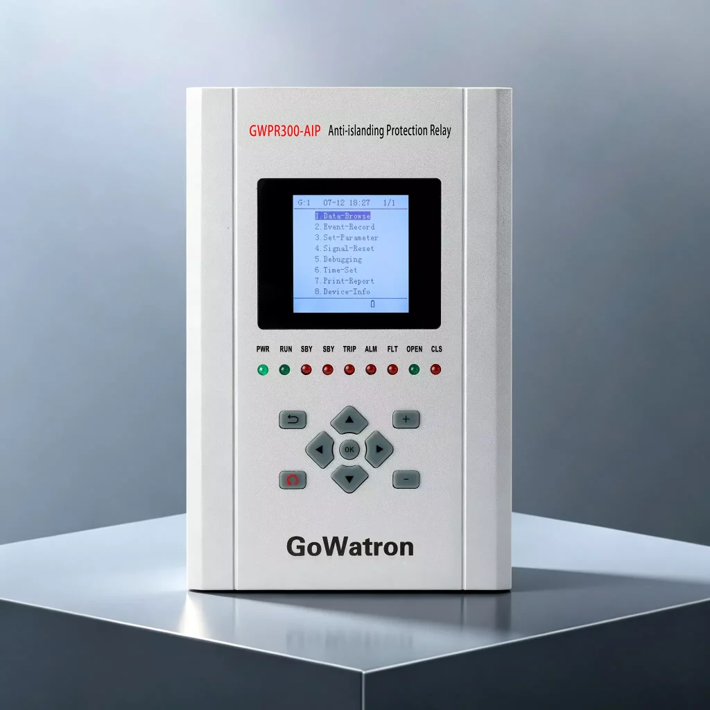
4.3 GWPR300-AIP Anti-Islanding Protection Relay
The GWPR300-AIP Anti-Islanding Protection Relay is designed for higher-voltage and utility-scale photovoltaic grid interconnection applications.
Typical Applications
- 33 kV Solar Farms
- 66 kV Renewable Energy Substations
- 132 kV PV Grid Connection
- Utility-Scale Solar Power Plants
- Renewable Energy Grid Interconnection Substations
Key Features
- Anti-Islanding Protection
- (ANSI 27/59) Multi-stage Voltage Protection
- (ANSI 81U/81O) Multi-stage Frequency Protection
- (ANSI 81R) ROCOF Protection
- (ANSI 50/51) Multi-stage Overcurrent Protection
- (ANSI 67) Directional Overcurrent Protection
- (ANSI 51N) Zero-Sequence Overcurrent Protection
- (ANSI 59N) Zero-Sequence Overvoltage Protection
- (ANSI 32R) Reverse Power Protection
- VT Circuit Failure Detection
- Harmonic Detection
- External Trip / Intertrip
- Event and Fault Waveform Recording
- Dual Ethernet and RS-485 Communication Interfaces
- IEC 60870-5-104 Communication Protocol
- Modbus RTU Communication Protocol
- Optional IEC 61850 Communication Protocol
- IRIG-B and SNTP Time Synchronisation
The GWPR300-AIP is suitable for utility-scale PV projects requiring comprehensive grid interconnection protection, measurement, communication, event recording, and integration with higher-level automation systems.
5. Comparison of GWPR100-AIP, GWPR200-AIP and GWPR300-AIP
| Model | Grid Connection Voltage | Typical Application | Communication |
| GWPR100-AIP | 400 V | Distributed and rooftop PV | RS-485 / Modbus RTU |
| GWPR200-AIP | 11 kV / 22 kV | Medium-voltage distributed PV | IEC 60870-5-103 over Ethernet / Modbus RTU |
| GWPR300-AIP | 33 kV / 66 kV / 132 kV | Utility-scale PV and substations | IEC 60870-5-104 / Modbus RTU / Optional IEC 61850 |
6. Difference Between Anti-Islanding Protection and Fault Isolation Protection
Anti-islanding protection and fault isolation protection may both be required at a PV grid connection point, but their protection objectives are different.
Anti-Islanding Protection
Its primary purpose is to:
- Detect an islanding condition
- Identify abnormal grid conditions associated with loss of the utility source
- Disconnect PV generation from the isolated network
Fault Isolation Protection
Its primary purpose is to:
- Detect specified grid-side faults or abnormal grid conditions
- Initiate isolation from the affected network section
- Prevent the PV plant from remaining connected to the specified faulted section
The two schemes may monitor some of the same electrical quantities, but their protection objectives, operating criteria, setting logic, and coordination requirements are different.
Neither should automatically be treated as a substitute for the other.
The final configuration should follow the utility interconnection requirements and project protection philosophy.
7. Complete PV Grid Connection Protection Panel
A standalone anti-islanding protection relay may be sufficient for some distributed PV projects.
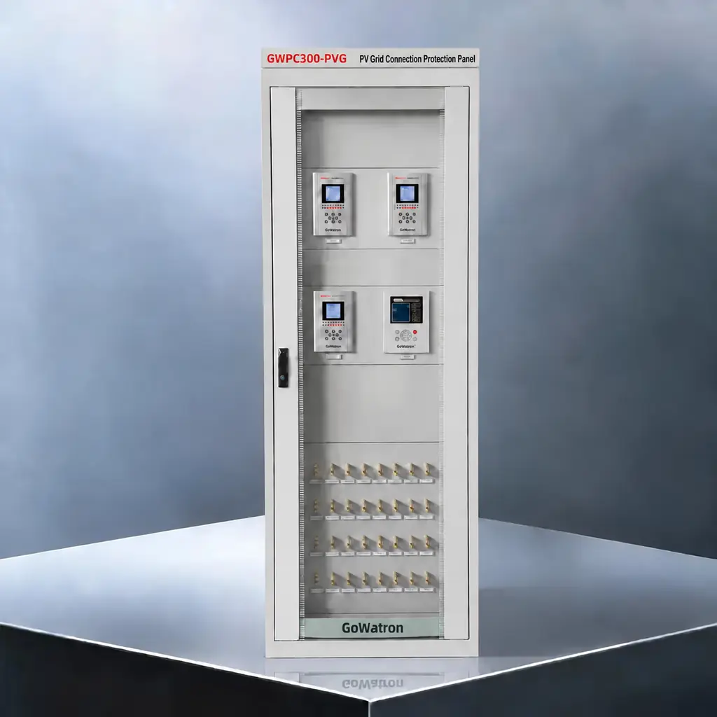
Larger PV plants may require several dedicated protection, monitoring, metering, control, and communication devices at the grid interconnection point.
Depending on project requirements, a complete PV grid connection protection system may include:
- Anti-Islanding Protection Relay
- Fault Isolation Relay
- Frequency and Voltage Protection & Control Relay
- Power Quality Monitoring Device
- Metering Device
- Communication Management Device
7.1 Frequency and Voltage Protection & Control
An anti-islanding protection relay already includes voltage and frequency protection elements such as ANSI 27, 59, 81U, and 81O.
A dedicated Frequency and Voltage Protection & Control Relay is therefore not added simply to duplicate these basic protection elements.
When required by the utility or project protection scheme, it can provide independent staged frequency and voltage protection and control functions, such as:
- Multi-stage underfrequency control
- Multi-stage overfrequency control
- Multi-stage undervoltage control
- Multi-stage overvoltage control
- Load-shedding logic
- Generation-shedding logic
- Trip and control output coordination
For example, if system frequency continues to decrease through several predefined thresholds, different stages can initiate sequential load shedding according to the approved control strategy.
For a PV power plant, abnormal frequency or voltage conditions may also initiate staged generation reduction or disconnection where required by the utility protection and control scheme.
The number of stages, pickup thresholds, time delays, controlled feeders or generation blocks, and output logic are project-specific and should be determined by the utility requirements and system study.
Therefore, a separate Frequency and Voltage Protection & Control Relay is project-dependent and is not mandatory for every PV grid connection system.
7.2 Communication Protocol Selection
Communication requirements depend on the relay model and project SCADA/SAS architecture.
GWPR100-AIP
Interface: RS-485
Protocol: Modbus RTU
This configuration is suitable for compact low-voltage distributed PV applications.
GWPR200-AIP
Interfaces: Ethernet + RS-485
Protocols: IEC 60870-5-103 over Ethernet + Modbus RTU
The Ethernet interface is used for IEC 60870-5-103 over Ethernet, while RS-485 supports Modbus RTU.
GWPR300-AIP
Interfaces: Dual Ethernet + RS-485
Protocols: IEC 60870-5-104 + Modbus RTU + Optional IEC 61850
This configuration is intended for applications requiring broader SCADA or substation automation integration.
The communication differences between the three models reflect their different hardware and system-integration configurations. The final protocol should be selected according to the actual project communication architecture rather than voltage level alone.
7.3 GWPC300-PVG PV Grid Connection Protection Panel
For projects requiring an integrated secondary-system solution, GoWatron provides the GWPC300-PVG PV Grid Connection Protection Panel.
The product hierarchy is:
GWPR100-AIP / GWPR200-AIP / GWPR300-AIP → Anti-Islanding Protection Relays
GWPC300-PVG → PV Grid Connection Protection Panel
Depending on project requirements, the GWPC300-PVG can integrate:
- Anti-Islanding Protection
- Fault Isolation Protection
- Frequency and Voltage Protection & Control
- Power Quality Monitoring
- Metering
- Communication Management
Compared with installing individual devices separately, an integrated panel can simplify secondary-system engineering, panel wiring, inter-device signal coordination, factory testing, on-site installation, commissioning, and SCADA integration.
8. Anti-Islanding Protection Relay Selection by Voltage Level
- 400 V — GWPR100-AIP Low-Voltage Anti-Islanding Protection Relay
For low-voltage distributed PV, commercial rooftop PV, industrial rooftop PV, and other 400 V grid-connected photovoltaic applications. - 11 kV / 22 kV — GWPR200-AIP Anti-Islanding Protection Relay
For medium-voltage commercial, industrial, and distributed PV grid connection projects. - 33 kV / 66 kV / 132 kV — GWPR300-AIP Anti-Islanding Protection Relay
For utility-scale solar farms, renewable energy substations, and higher-voltage PV grid interconnection applications. - Complete PV Grid Connection Solution — GWPC300-PVG PV Grid Connection Protection Panel
For projects requiring integrated protection, monitoring, metering, control, and communication functions within a coordinated panel solution.
9. Information Required for Anti-Islanding Relay Selection
Before selecting an anti-islanding protection relay or requesting a quotation, provide the following project information where possible:
- Grid connection voltage
- PV plant capacity
- System frequency — 50 Hz or 60 Hz
- CT ratio
- VT ratio
- Required protection functions
- Applicable utility requirements or grid code
- Required communication interfaces
- Required communication protocols
- SCADA or substation automation requirements
- Required digital inputs and outputs
- Installation method
- Standalone relay or complete PV grid connection protection panel requirement
Providing this information helps determine the appropriate relay model, protection configuration, hardware, communication interfaces, protocols, and overall system solution.
10. Anti-Islanding Protection Relay Selection Summary
| Grid Connection | Recommended Product | Recommended Application |
| 400 V | GWPR100-AIP Low-Voltage Anti-Islanding Protection Relay | Distributed and rooftop PV |
| 11 kV / 22 kV | GWPR200-AIP Anti-Islanding Protection Relay | Medium-voltage distributed PV |
| 33 kV / 66 kV/ 132 kV | GWPR300-AIP Anti-Islanding Protection Relay | Utility-scale solar farms and renewable energy substations |
| Complete PV Grid Connection System | GWPC300-PVG PV Grid Connection Protection Panel | Integrated protection, monitoring, metering and communication |
- or a 400 V distributed PV system, the GWPR100-AIP provides a compact low-voltage anti-islanding protection solution.
- For 11 kV and 22 kV PV projects, the GWPR200-AIP provides anti-islanding and grid interconnection protection together with IEC 60870-5-103 over Ethernet and Modbus RTU communication.
- For 33 kV, 66 kV, and 132 kV solar projects, the GWPR300-AIP provides a more comprehensive protection and communication platform with IEC 60870-5-104, Modbus RTU, and optional IEC 61850.
- Where multiple protection, monitoring, metering, control, and communication devices need to be integrated into one coordinated system, the GWPC300-PVG PV Grid Connection Protection Panel provides a panel-level solution.
- Final relay selection, protection settings, and control logic should always be determined according to the applicable grid code, utility requirements, system studies, and project-specific protection coordination.


