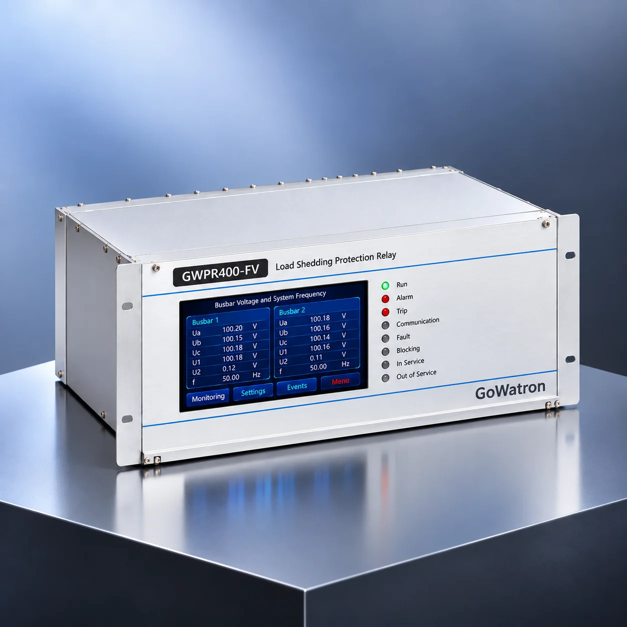
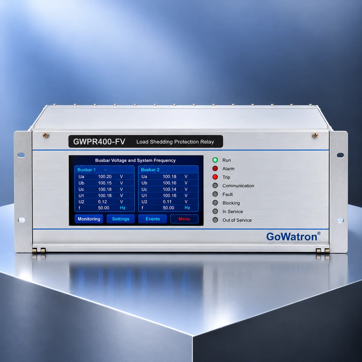
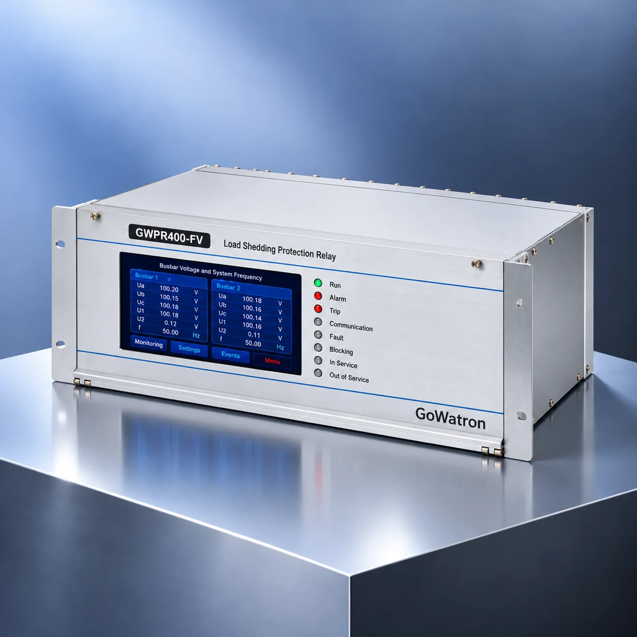
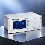
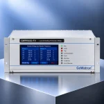
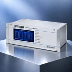
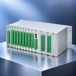
GWPR400-FV Underfrequency / Undervoltage Protection and Load Shedding Relay
- The GWPR400-FV Underfrequency and Undervoltage Protection and Load Shedding Relay is a numerical protection and control relay designed to support power system frequency and voltage stability. It integrates underfrequency protection (ANSI 81U), undervoltage protection (ANSI 27), automatic load shedding, accelerated load shedding based on the rate of change of frequency (df/dt) and the rate of change of voltage (dU/dt), voltage transformer (VT) circuit failure supervision and protection blocking functions.
- The GWPR400-FV relay monitors the voltage of two busbar sections and provides eight underfrequency load-shedding stages and eight undervoltage load-shedding stages, each comprising five basic stages and three special stages. Its programmable trip output matrix supports up to 60 load feeder circuits in total, enabling selective load disconnection to reduce the risk of frequency and voltage instability.
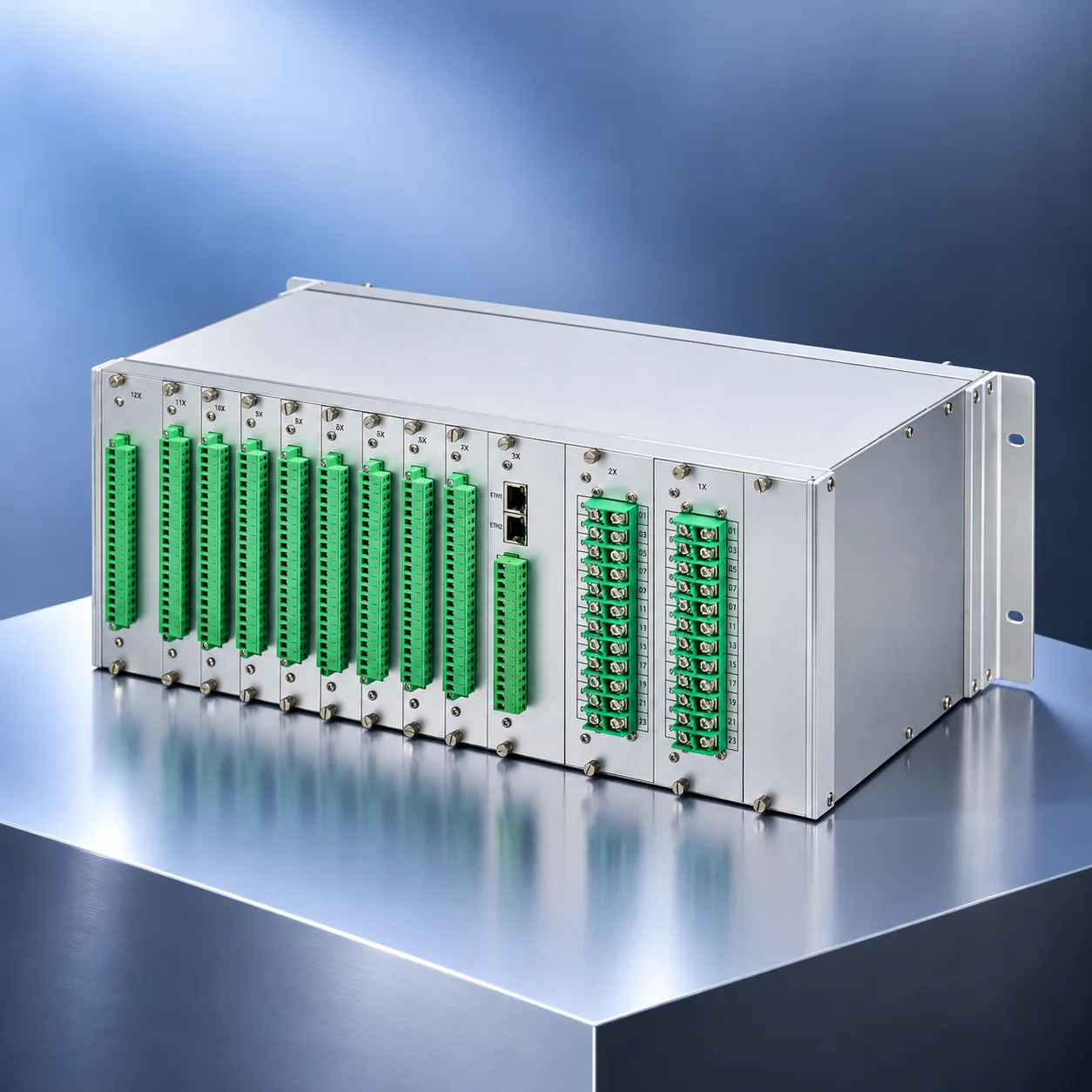
- The relay provides two Ethernet ports and one RS-485 interface, supporting IEC 60870-5-103, IEC 60870-5-104 and Modbus communication protocols, with optional IEC 61850. NTP and IRIG-B time synchronisation are also supported. The GWPR400-FV relay can be integrated into substation automation systems (SAS) and SCADA platforms for remote monitoring, event recording, disturbance recording and operational data transmission.




1. Product Introduction
- The GWPR400-FV relay employs numerical protection technology to continuously monitor system frequency and busbar section voltages. When an active power deficit causes the system frequency to decline, or insufficient reactive power support contributes to voltage instability, the relay automatically disconnects predefined loads according to configured pickup settings, operating delays and load-shedding priorities.
- The relay uses a multi-stage load-shedding scheme with independently configurable pickup settings, operating delays and stage enable/disable settings. Its programmable trip output matrix enables flexible allocation of load feeders to individual stages.
- Additional functions, including df/dt and dU/dt accelerated load shedding, prevention of excessive load disconnection and fault-related blocking, improve operating selectivity and reliability under different power system configurations and operating conditions.
2. Protection and Control Functions
2.1 Underfrequency Protection and Load Shedding (ANSI 81U)
When an active power deficit causes the system frequency to decrease, the GWPR400-FV relay disconnects selected loads according to predefined frequency pickup settings and operating delays, helping restore the balance between power generation and demand.
- Five basic stages and three special stages, providing eight underfrequency load-shedding stages.
- Independently configurable frequency pickup settings, operating delays and stage enable/disable settings.
- Underfrequency pickup setting range: 45–50 Hz.
- Frequency recovery supervision to prevent unnecessary further load shedding.
- Programmable trip output assignment for individual load-shedding stages.
2.2 Accelerated Underfrequency Load Shedding (df/dt)
The GWPR400-FV relay monitors df/dt to identify rapid frequency declines. When the configured acceleration criteria are satisfied and no applicable blocking condition is active, additional loads can be disconnected earlier to help arrest the frequency decline and reduce the risk of system instability.
The relay supports two selectable acceleration modes:
- Mode 1: Acceleration of Stage 2 when Stage 1 operates.
- Mode 2: Acceleration of Stages 2 and 3 when Stage 1 operates.
The acceleration function also provides:
- Configurable df/dt acceleration thresholds and operating delays.
- Coordination with frequency recovery supervision and protection blocking functions.
The acceleration modes are alternative configurable schemes rather than two mandatory simultaneous operations. Accelerated operation requires the configured acceleration criteria to be satisfied and the corresponding blocking conditions to be inactive.
2.3 Undervoltage Protection and Load Shedding (ANSI 27)
The GWPR400-FV relay monitors the voltage of two busbar sections and initiates staged load shedding when sustained voltage reductions satisfy the configured operating conditions. Load disconnection reduces system loading and can support voltage recovery.
- Five basic stages and three special stages, providing eight undervoltage load-shedding stages.
- Independently configurable voltage pickup settings, operating delays and stage enable/disable settings.
- Undervoltage pickup setting range: 0.3–0.9 \(U_n\), where \(U_n\) is the rated reference voltage.
- Voltage monitoring and load-shedding control for two busbar sections.
- Programmable trip output assignment for individual load-shedding stages.
2.4 Accelerated Undervoltage Load Shedding (dU/dt)
The GWPR400-FV relay monitors dU/dt to identify rapid voltage deterioration. When the configured acceleration criteria are satisfied and no applicable blocking condition is active, predefined loads can be disconnected earlier to reduce system loading and mitigate further voltage decline.
The relay supports two selectable acceleration modes:
- Mode 1: Acceleration of Stage 2 when Stage 1 operates.
- Mode 2: Acceleration of Stages 2 and 3 when Stage 1 operates.
The acceleration function also provides:
- Configurable dU/dt acceleration thresholds and operating delays.
- Coordination with short-circuit fault blocking to prevent unintended load shedding during transient voltage dips.
The acceleration modes are alternative configurable schemes selected according to the required load-shedding strategy. Accelerated operation requires the configured acceleration criteria to be satisfied and the corresponding blocking conditions to be inactive.
2.5 Frequency and Voltage Rate-of-Change Blocking
The GWPR400-FV relay incorporates df/dt and dU/dt blocking functions to prevent inappropriate load-shedding operations during abnormal measurement conditions or fault-related transients.
- df/dt blocking: Inhibits underfrequency load shedding when the configured frequency rate-of-change blocking criterion is satisfied. Blocking is released when the specified frequency recovery conditions are met.
- dU/dt blocking: Inhibits undervoltage load shedding when the configured voltage rate-of-change blocking criterion is satisfied. Blocking is released when the specified voltage recovery conditions are met.
- Abnormal frequency blocking: Identifies measured frequencies below 40 Hz or above 60 Hz as abnormal and inhibits the relevant load-shedding functions.
- Low-voltage blocking: Inhibits the relevant frequency-dependent protection logic when the positive-sequence voltage falls below 0.15 \(U_n\), preventing unreliable frequency measurements from initiating load shedding.
Acceleration and blocking functions use separate settings and operating criteria. Accelerated load shedding is permitted only when the applicable acceleration criteria are satisfied and all relevant blocking conditions are inactive. Blocking takes precedence over the corresponding accelerated trip command.
2.6 Short-Circuit Fault Blocking and Blocking Release
Short-circuit faults can cause sudden and substantial busbar voltage dips. The GWPR400-FV relay uses voltage magnitude and rate-of-change criteria to distinguish fault-related voltage reductions from sustained undervoltage conditions requiring load shedding.
During identified short-circuit conditions, the relay blocks undervoltage load shedding to prevent unintended load disconnection. Following fault clearance, blocking is released when the configured voltage recovery conditions are satisfied.
- K1: Configurable short-circuit fault detection voltage threshold (setting range: 0.5–0.9 \(U_n\)).
- K2: Configurable post-fault voltage recovery threshold (setting range: 0.5–0.9 \(U_n\)).
- Tfc: Configurable fault clearance coordination time (setting range to be confirmed).
- Abnormal condition alarm when the voltage fails to recover within the specified period.
The Tfc setting range is to be confirmed against the final GWPR400-FV technical specification.
2.7 VT Circuit Failure Supervision, Blocking and Alarm
- The GWPR400-FV relay provides voltage transformer (VT) circuit failure supervision. When a VT circuit failure is detected, the relay issues an alarm and blocks the affected busbar section’s undervoltage load-shedding function to prevent unintended load disconnection caused by incorrect voltage measurements.
- In the reference device configuration, VT circuit failure detection uses a negative-sequence voltage criterion.
- An alarm is initiated when the measured negative-sequence voltage exceeds 10 V (secondary) for 3 s. The alarm automatically resets 5 s after the abnormal condition disappears.
2.8 Split-Busbar and Paralleled-Busbar Operation
The GWPR400-FV relay supports voltage monitoring for two busbar sections and configurable load-shedding logic for different busbar operating arrangements.
- Split-busbar operation: Each busbar section is monitored independently, with separate frequency and voltage assessments and corresponding load-shedding outputs.
- Paralleled-busbar operation: Load-shedding commands can be assigned to the relevant outputs of both busbar sections.
- Independent stage enable/disable settings for the applicable busbar sections.
The operating arrangement can be configured according to the actual busbar configuration and system operating requirements.
2.9 Eight-Stage Load Shedding and Programmable Trip Output Matrix
The GWPR400-FV relay provides eight stages for each underfrequency and undervoltage load-shedding function, comprising five basic stages and three special stages.
Each stage can be configured with its own pickup settings, operating delays and trip output assignments.
- Supports up to 60 load feeder circuits in total.
- Programmable assignment of trip outputs to individual load-shedding stages.
- Flexible allocation of feeder circuits without a fixed number of feeders per stage.
- Selective and sequential load disconnection according to predefined load priorities.
- Independent stage enable/disable settings for the underfrequency and undervoltage functions respectively.
The number of load feeders assigned to each stage can be configured according to the required load-shedding capacity and operating strategy.
2.10 Communication, Time Synchronisation and Event Recording
The GWPR400-FV relay provides two Ethernet ports and one RS-485 interface for integration into substation automation systems and SCADA platforms.
- IEC 60870-5-103, IEC 60870-5-104 and Modbus communication protocols.
- Optional IEC 61850 communication.
- Remote transmission of measurements, operating status, alarms and load-shedding events.
- NTP and IRIG-B time synchronisation.
- Sequence of Events (SOE) and operation records.
- COMTRADE disturbance recording for post-event analysis.
- Colour touchscreen HMI for operating status monitoring, protection setting configuration and event review.
3. Technical Specifications
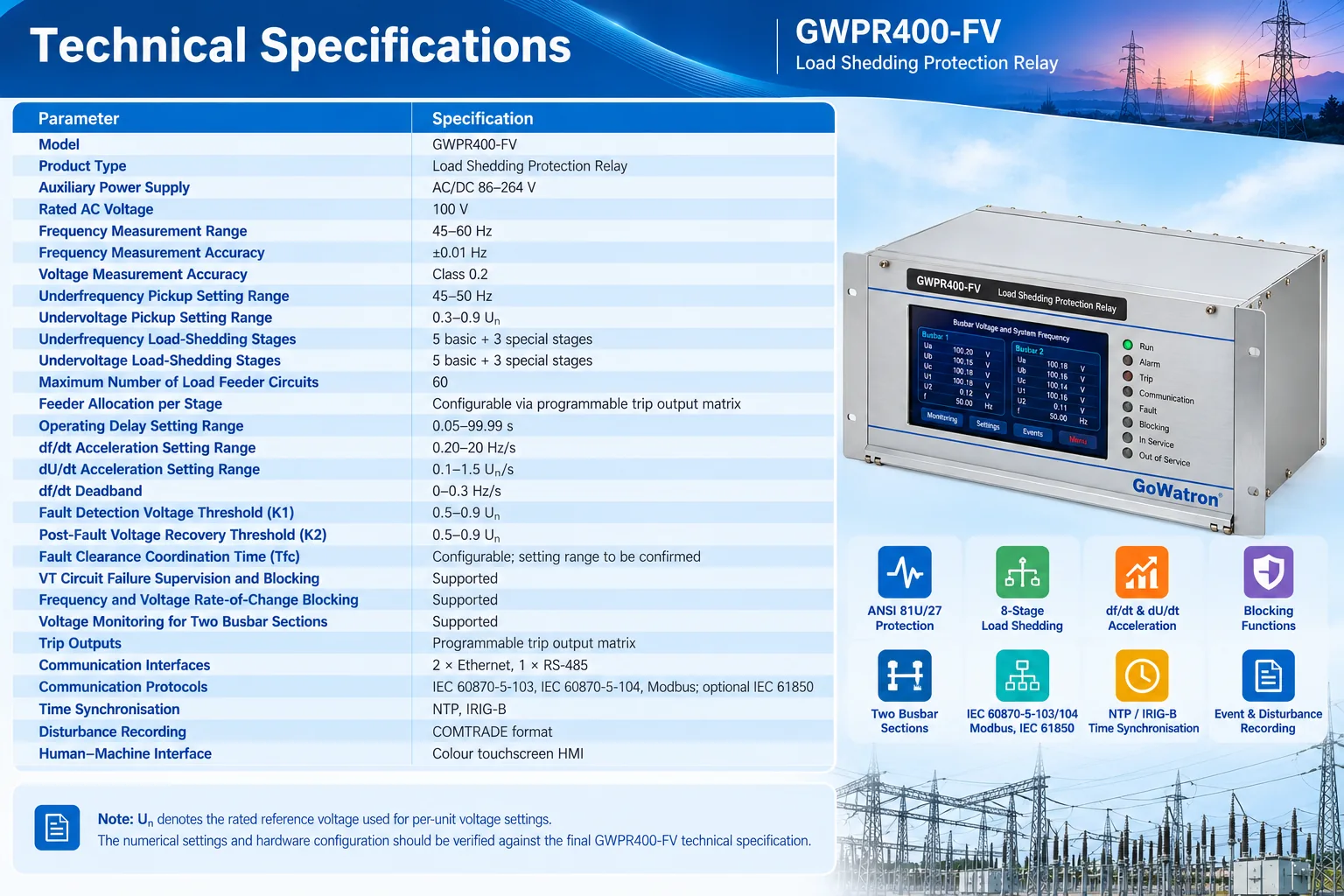
4. Operating Principle
4.1 Underfrequency Protection and Load Shedding Operating Principle
When generator tripping, interconnection outages or insufficient active power generation cause the system frequency to decline, the GWPR400-FV relay continuously monitors the measured frequency and compares it with the configured pickup settings for each underfrequency load-shedding stage.
The basic operating criteria are:
\[ f \leq f_{n,\mathrm{set}} \]
Where:
- \(f\): Measured system frequency (Hz).
- \(f_{n,\mathrm{set}}\): Frequency pickup setting of Stage \(n\) (Hz).
- \(t\): Elapsed time for which the applicable operating condition remains satisfied (s).
- \(T_{f,n}\): Operating delay of Stage \(n\) (s).
An optional supplementary frequency-direction criterion may be applied:
\[ \frac{df}{dt} \leq 0 \]
Where \(df/dt\) is the rate of change of frequency (Hz/s).
- This supplementary criterion indicates that the frequency is decreasing or not increasing. It is not a mandatory condition for all underfrequency load-shedding schemes and should only be applied where required by the configured relay logic.
- When the applicable operating criteria are satisfied and no blocking condition is active, the GWPR400-FV relay issues trip commands to disconnect the assigned load feeders.
- If the frequency decline reaches the configured df/dt acceleration threshold, the relay can accelerate Stage 2 or Stages 2 and 3 according to the selected acceleration mode, provided that the corresponding blocking conditions are inactive.
- Frequency recovery supervision helps prevent unnecessary further load shedding.
4.2 Undervoltage Protection and Load Shedding Operating Principle
When insufficient reactive power support contributes to sustained busbar voltage deterioration, the GWPR400-FV relay monitors the measured busbar section voltage and compares it with the configured pickup settings for each undervoltage load-shedding stage.
The basic operating criteria are:
\[ U \leq U_{n,\mathrm{set}} \]
\[ t \geq T_{U,n} \]
Where:
- \(U\): Measured busbar section voltage (V).
- \(U_{n,\mathrm{set}}\): Voltage pickup setting of Stage \(n\) (V).
- \(t\): Elapsed time for which the applicable operating condition remains satisfied (s).
- \(T_{U,n}\): Operating delay of Stage \(n\) (s).
When the voltage remains below the configured pickup setting for the specified operating delay, and no blocking condition is active, the relay disconnects the assigned loads.
An optional supplementary voltage-direction criterion may be applied where required by the configured relay logic. Accelerated load shedding based on dU/dt may be initiated as described in Section 2.4, provided that the corresponding blocking conditions are inactive.
During identified short-circuit faults, the relay applies blocking logic to prevent unintended operation caused by transient voltage dips.
Following fault clearance, blocking is released when the configured voltage recovery conditions are satisfied.
4.3 Multi-Stage Load Shedding Operating Principle
- The GWPR400-FV relay uses an eight-stage load-shedding scheme for each underfrequency and undervoltage function, comprising five basic stages and three special stages.
- Each stage has independently configurable pickup settings, operating delays and stage enable/disable settings.
- Through the programmable trip output matrix, individual stages can be assigned to selected load feeder circuits, supporting up to 60 load feeders in total.
- Non-critical and interruptible loads are generally allocated to earlier stages. If the system frequency or voltage continues to deteriorate, additional predefined loads are disconnected when subsequent stage operating criteria are satisfied.
- The load-shedding scheme should be designed according to power system stability studies, load criticality assessments, available interruptible load capacity and applicable grid operator requirements.
5. Applications
5.1 Substation Automatic Load Shedding Systems
- The GWPR400-FV relay is suitable for system frequency and busbar section voltage monitoring, as well as automatic load shedding across multiple feeders in substations.
- It supports multi-stage load disconnection to reduce the risk of system frequency or voltage instability during major disturbances.
5.2 Power Plants and Captive Power Systems
- The GWPR400-FV relay provides automatic load shedding following generator outages or active power deficits.
- It helps maintain frequency stability in power plant auxiliary systems, captive power systems and local electrical networks by disconnecting predefined non-critical loads when required.
5.3 Industrial Power Distribution Systems
- The GWPR400-FV relay is suitable for steelworks, petrochemical facilities, mines, cement plants and large manufacturing sites.
- Load-shedding priorities can be configured according to process criticality and operational requirements, helping reduce the risk of widespread outages and protect essential industrial loads.
5.4 Regional Power Networks and Islanded Power Systems
- The GWPR400-FV relay can be applied in regional power networks, isolated power systems and islanded operating conditions.
- Automatic load shedding helps restore the balance between power generation and demand and supports frequency and voltage stability during major system disturbances.
5.5 Renewable Energy Power Plants and Step-Up Substations
- The GWPR400-FV relay can be applied in renewable energy step-up substations and associated distribution systems where emergency load-shedding functions are required.
- It provides frequency and voltage monitoring and configurable load disconnection in accordance with the project’s power system stability control scheme.


