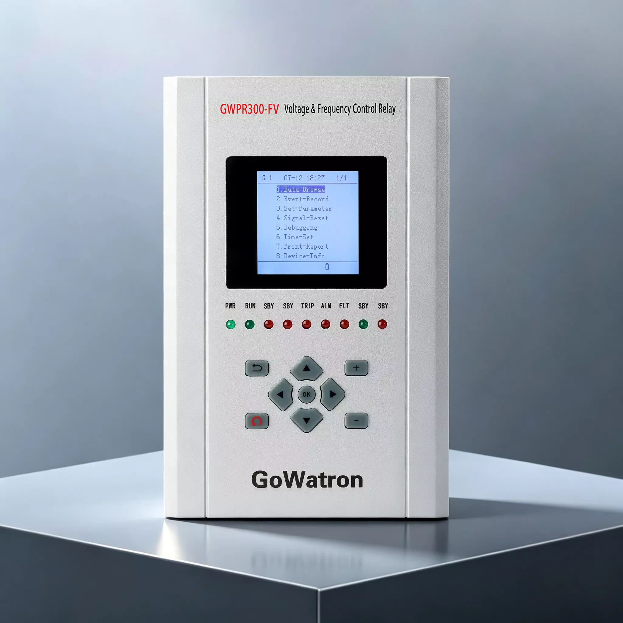
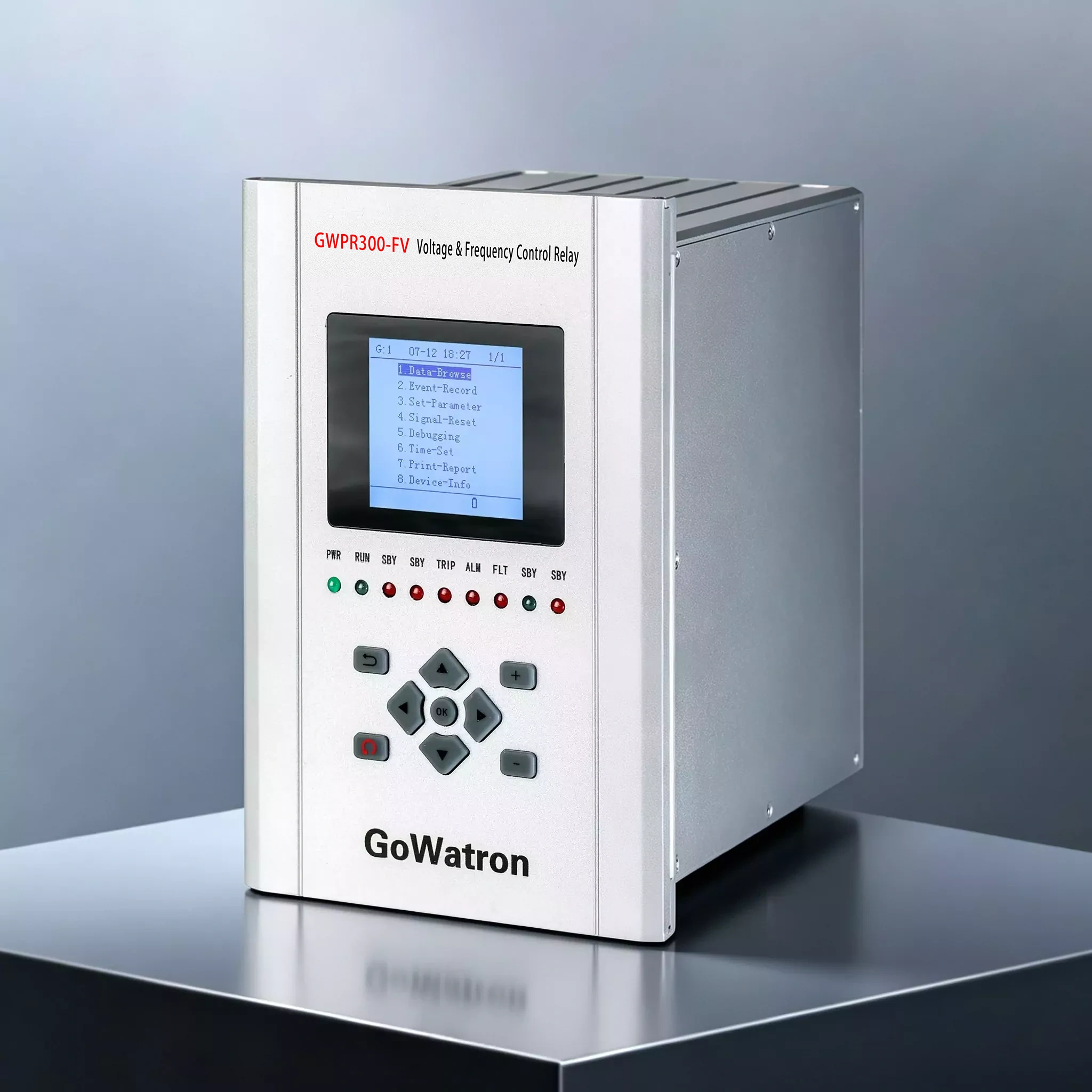
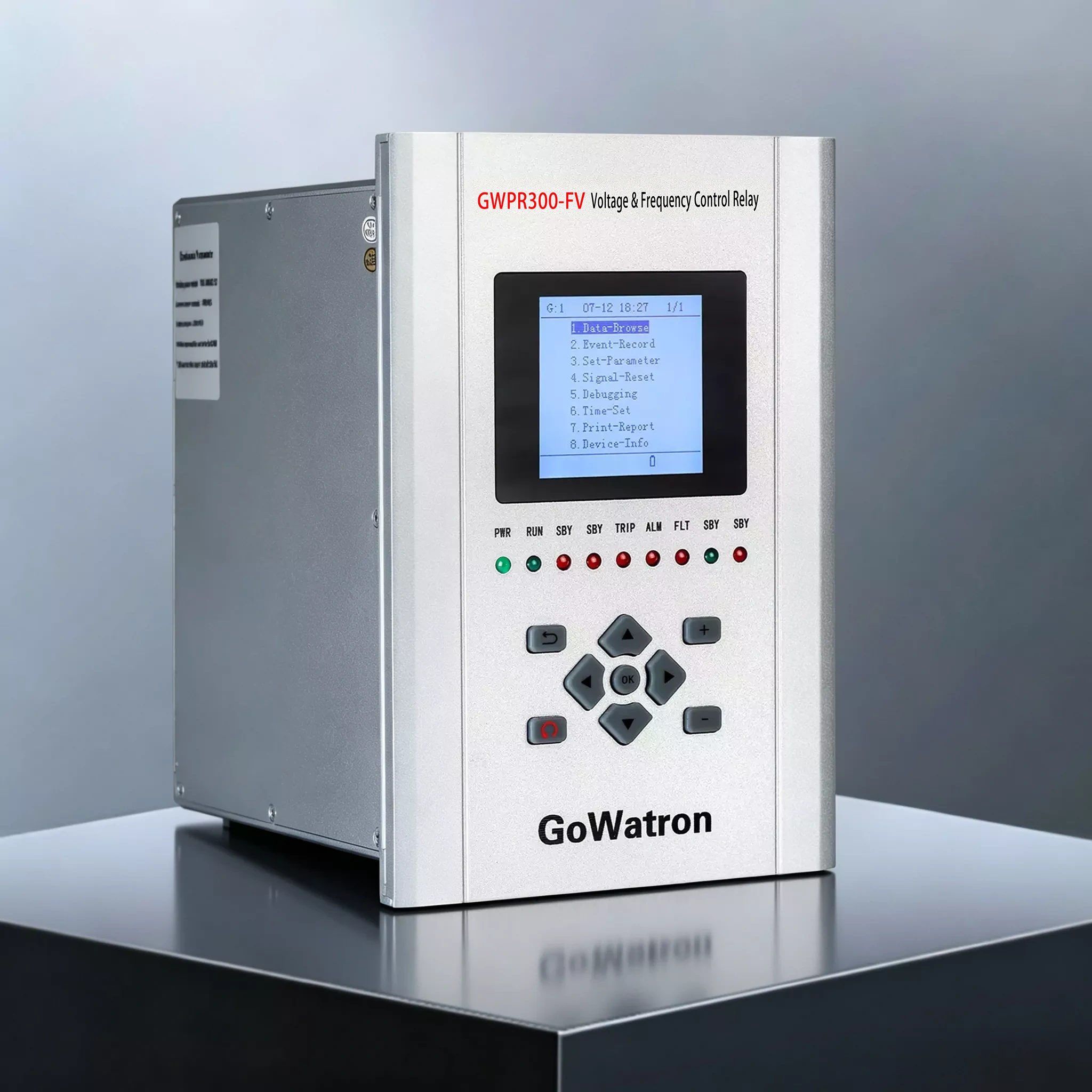



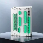
GWPR300-FV Voltage & Frequency Control Relay
The GWPR300-FV Voltage & Frequency Control Relay is designed for emergency control under abnormal grid frequency and voltage conditions. It provides three-stage underfrequency/overfrequency/undervoltage/overvoltage load-shedding tripping, and can also operate as a terminal execution device to execute remote trip commands or load-shedding commands issued by a regional stability control system.
Communication
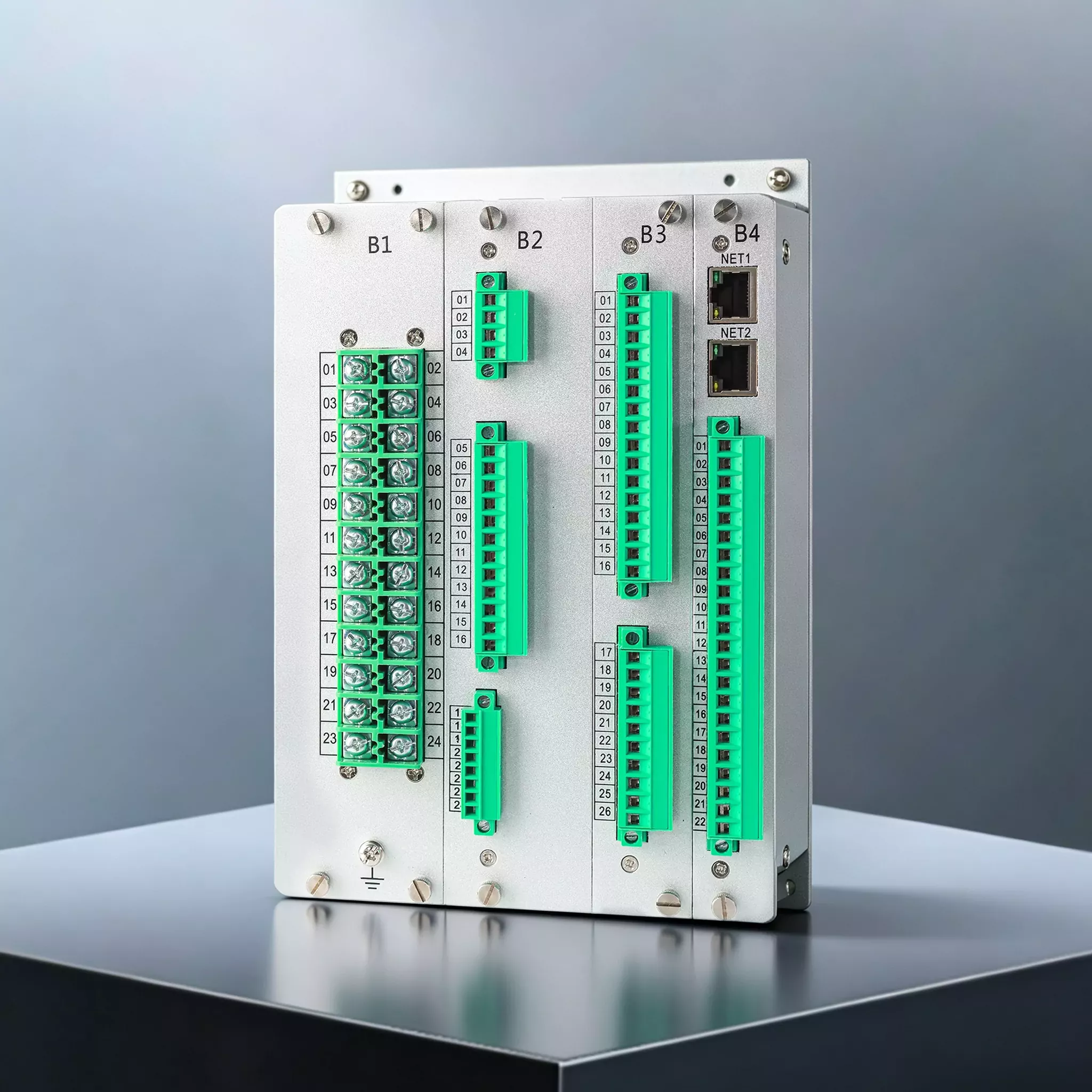
- 2 Ethernet ports (supporting IEC 60870-5-104 protocol)
- 2 Ethernet ports (optional, supporting IEC 61850 protocol)
- 1 RS-485 serial communication port (supporting Modbus RTU protocol)
- Time synchronisation: communication message time synchronisation, SNTP, IRIG-B
- Printing interface: supports a dot-matrix printer with serial communication (prints settings, event records and disturbance records)




Product Introduction
- The GWPR300-FV Voltage & Frequency Control Relay is a grid frequency and voltage emergency control device from GoWatron. The device employs a high-performance 32-bit microcontroller with integrated DSP and FPU, enabling real-time processing of all analogue quantities and binary inputs during each sampling interval, and efficiently performing protection algorithms, trip logic, event recording, disturbance recording and communication with the station control system.
- The device uses 16-bit independent A/D conversion for high-accuracy sampling, together with an abnormal-sample filtering algorithm to improve the interference immunity of AC signal acquisition. The hardware configuration is flexible, employing an internal high-speed bus for easy expansion and maintenance. The integral front panel and fully enclosed enclosure provide strict separation between high-voltage and low-voltage circuits. Anti-interference measures are incorporated into both the hardware and software design to enhance electromagnetic compatibility, while electromagnetic emissions comply with the relevant standards.
- The device supports 6 voltage inputs (three-phase voltages of Sections I and II), 21 voltage-operated binary inputs, 13 independent relay outputs and 1 device power-failure signal output. It features a user-friendly human-machine interface and convenient on-site device testing functions. All protection elements are designed as independent functional modules and can be flexibly configured.
Product Functions
Protection Functions (Trip/Alarm)
Sections I and II refer to the two independent voltage/frequency measurement sections; Stage 1/2/3 refer to the three load-shedding stages within each section.
- (ANSI 27) Undervoltage protection / Section I Stage 1/2/3, Section II Stage 1/2/3 (trip)
- (ANSI 59) Overvoltage protection / Section I Stage 1/2/3, Section II Stage 1/2/3 (trip)
- (ANSI 81U) Underfrequency protection / Section I Stage 1/2/3, Section II Stage 1/2/3 (trip)
- (ANSI 81O) Overfrequency protection / Section I Stage 1/2/3, Section II Stage 1/2/3 (trip)
- (ANSI 60) VT circuit failure / Section I, Section II (alarm)
Operating Logic Highlights:
- (ANSI 27) Undervoltage protection: all line-to-line voltages ≤ setting; after the corresponding stage delay, the associated trip output and fault-signal output are activated; the protection resets when the voltage rises above 1.05 times the setting.
- (ANSI 59) Overvoltage protection: any line-to-line voltage ≥ setting; after the corresponding stage delay, the associated trip output and fault-signal output are activated; the protection resets when the voltage falls below 0.95 times the setting.
- (ANSI 81U) Underfrequency protection: f ≤ setting; undervoltage blocking and rate-of-change-of-frequency (ROCOF) blocking may be enabled; the protection resets when the frequency rises above the underfrequency protection setting.
- (ANSI 81O) Overfrequency protection: f ≥ setting; undervoltage blocking and rate-of-change-of-frequency (ROCOF) blocking may be enabled; the protection resets when the frequency falls below the overfrequency start setting.
- (ANSI 60) VT circuit failure: positive-sequence voltage U1 < 0.3Un or negative-sequence voltage U2 > 0.08Un, with duration ≥ the VT circuit failure delay; alarm signal relay 13 (B325/B326) operates, an alarm message is displayed on the liquid crystal display (LCD), and the alarm LED on the front panel illuminates (manual reset required).
The three stages operate according to load priority; in general, lower-priority loads are shed first and higher-priority loads later. Accordingly, the delays are typically set as Stage 1 < Stage 2 < Stage 3.
- Measurement and Control Functions
- Voltage: Ua1, Ub1, Uc1, Uab1, Ubc1, Uca1, Ua2, Ub2, Uc2, Uab2, Ubc2, Uca2
- Frequency: f1, f2
- 21 voltage-operated binary inputs (AC/DC 220 V, DC 110 V or DC 48 V; to be specified when ordering)
- 13 independent relay outputs, 1 device power-failure signal output
Recording Functions
- Protection events: records the operating time, operating value and protection function name; up to 128 records
- Alarm events: records the operating time, operating value and protection function name; up to 128 records
- Binary input events: records binary input status changes; up to 128 records
- Operation records: records operations including setting modifications and protection enable/disable operations; up to 128 records
- Self-supervision events: records device self-supervision events; up to 32 records
- Disturbance records: records waveforms corresponding to protection operation events; up to 32 records
- Time Synchronisation and Printing
- Time synchronisation: communication message time synchronisation, SNTP, IRIG-B
- Printing: supports a dot-matrix printer with serial communication; prints settings, event records and disturbance records
3. Product Features
- Employs a high-performance 32-bit microcontroller with integrated DSP and FPU, efficiently performing protection algorithms, trip logic, event recording, disturbance recording and communication with the station control system; the high-performance hardware enables real-time processing of all analogue quantities and binary inputs during each sampling interval.
- Uses 16-bit independent A/D conversion for high-accuracy sampling, together with an abnormal-sample filtering algorithm to improve the interference immunity of AC signal acquisition.
- Flexible hardware configuration with an internal high-speed bus, facilitating expansion and maintenance.
- User-friendly human-machine interface with convenient on-site device testing functions.
- Comprehensive protection functions; all protection elements are designed as independent functional modules and can be flexibly configured.
- Integral front panel and fully enclosed enclosure with strict separation between high-voltage and low-voltage circuits; anti-interference measures are incorporated into both the hardware and software design to enhance electromagnetic compatibility, while electromagnetic emissions comply with the relevant standards.
- Extensive external interfaces, including dual Ethernet ports, an RS-485 serial communication port and an IRIG-B time synchronisation interface.
- Supports 21 voltage-operated binary inputs, 13 independent relay outputs and 1 device power-failure signal output.
- Supports IEC 60870-5-104 and Modbus RTU protocols, with IEC 61850 available as an option.
Typical Applications
- Grid voltage and frequency emergency control applications
- Applications requiring emergency control under abnormal grid frequency or voltage conditions
- Operation as a terminal execution device for remote trip commands
- Operation as a terminal execution device for load-shedding commands from regional stability control systems
- Load-shedding applications requiring staged disconnection according to load priority (three-stage undervoltage, overvoltage, underfrequency and overfrequency tripping)
- Substation and power plant automation applications requiring VT circuit failure alarms, disturbance recording and event recording


