Differences Between Anti-Islanding Protection Relay and Fault Separation Relay
Document Type: Technical Articles
Document Published: 2026-08-14
Last Updated: 2026-08-14
Scope of Application
- This document covers grid-connected protection configuration analysis for distributed energy resources (photovoltaic, energy storage, small hydropower stations and captive power plants) with a nominal voltage of 11 kV and below.
- It excludes safety stability control equipment, including high-frequency generator tripping and out-of-step splitting devices for large generating units at 132 kV and above.
I. General Summary of Core Differences Between Fault Separation Relay and Anti-Islanding Protection Relay
- Although both relays ultimately trip the grid-connected circuit breaker to isolate the power source from the utility grid, their protection objectives, triggering scenarios, detection principles, setting logic, and applicable standards are entirely distinct. Neither device can serve as a substitute for the other.
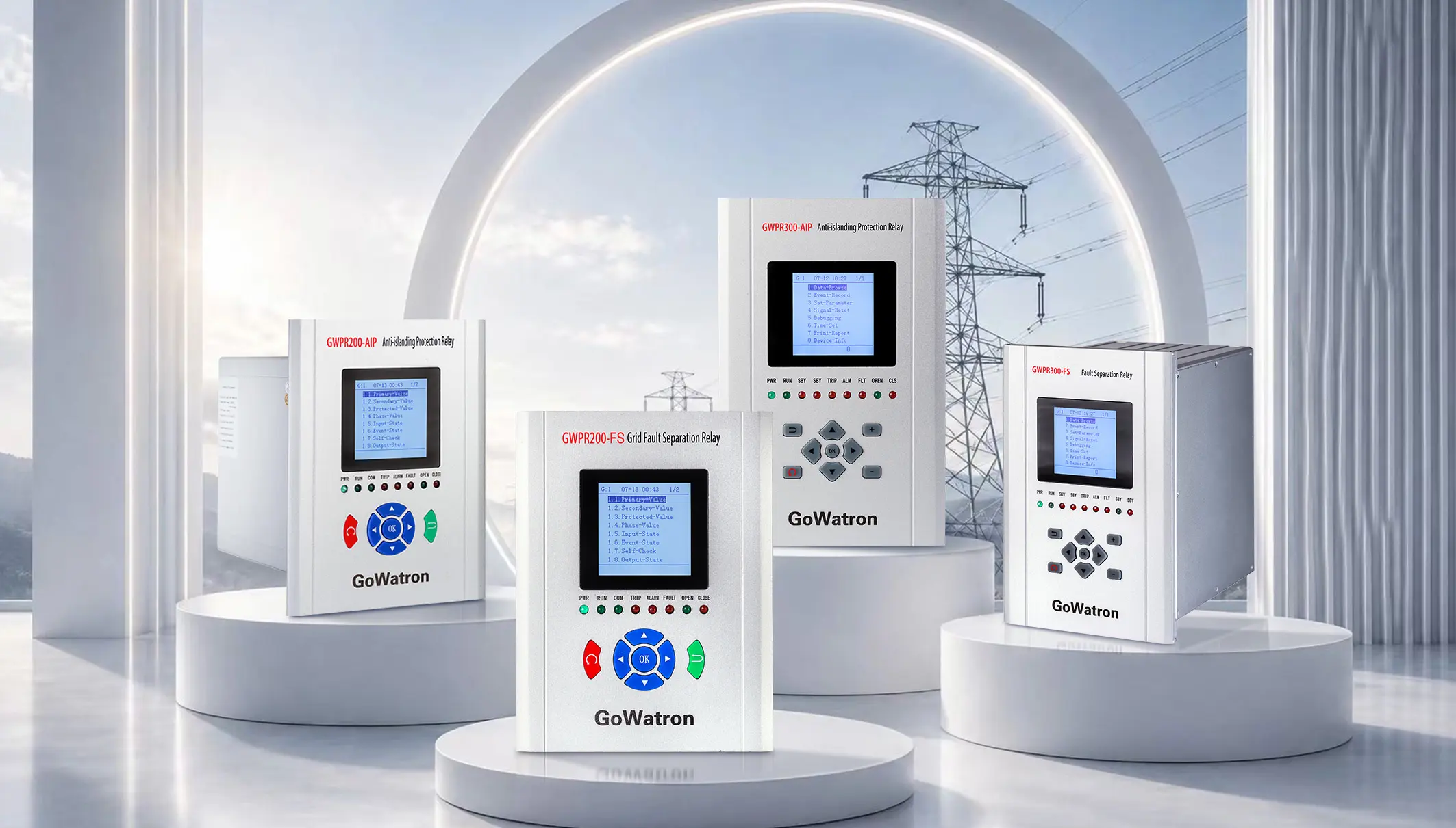
II. One-Sentence Core Definitions
Anti-Islanding Protection Relay
- Objective: To prevent distributed generators from continuing to supply local loads after the utility grid is disconnected, avoiding the formation of an unintentional island.
- Trigger Scenario: Main grid line tripping or scheduled outage. Photovoltaic, small hydropower or energy storage systems continue to export power, creating an island condition.
- Primary Risks: Electric shock hazards to maintenance personnel, out-of-phase reclosing impact, and voltage/frequency instability within the island that may damage equipment.
Fault Separation Relay
- Objective: To promptly disconnect distributed sources during grid disturbances or faults, maintain main grid stability and prevent fault escalation.
- Trigger Scenario: System short circuits, power oscillations, or sustained voltage/frequency depression. Distributed sources feed reverse current into fault points and worsen grid disturbances.
- Primary Risks: Fault propagation across the system, cascading outages, and voltage/frequency collapse.
III. Detailed Characteristic Descriptions
Anti-Islanding Protection Relay
- Core Mission: Prioritize personal safety; eliminate unintentional island operation.
- Typical Trigger Scenario: Loss of main grid supply. The Point of Common Coupling (PCC) loses bulk grid support, and the distributed generator forms an isolated system together with local loads.
- Detection Principle: Employs passive criteria (over/under voltage, over/under frequency) combined with active signal injection (the defining feature). The relay actively injects frequency or phase perturbations to overcome the Non-Detection Zone (NDZ) under power-balance conditions. When distributed generation output closely matches local load demand, passive voltage/frequency protection will operate within the NDZ and fail to trip. Only active signal injection can break the power equilibrium and reliably trigger protection operation.
- Action Logic Focus: Accurately identify islanding conditions and trip rapidly after grid disconnection. Protection logic shall coordinate strictly with reclosing and automatic transfer schemes to avoid maloperation. Automatic reclosing of the grid-connection circuit breaker shall be blocked upon anti-islanding protection operation. Without synchronism verification, unsynchronized reclosing will generate electrical impact equivalent to a three-phase short-circuit fault.
- Governing Standards: Chinese standards NB/T 11054, GB/T 33982, and international standards IEEE 1547, UL 1741 and series standards for distributed generation interconnection.
- Typical Applications: Grid-connected installations of distributed photovoltaic, energy storage, 11 kV and below distributed sources.
- Operating Time: Standards generally require an operating time ≤ 2 seconds, coordinated with the inverter Low Voltage Ride-Through (LVRT) capability.
- Key Feature: Equipped with built-in active islanding detection. Its protection scope covers only isolated systems formed after utility grid disconnection.
Fault Separation Relay
- Core Mission: Prioritize grid stability; isolate faults and restrict the spread of main grid disturbances.
- Typical Trigger Scenarios: Grid short-circuit faults, sustained system voltage/frequency deviations and system out-of-step oscillations.
- Detection Principle: Relies solely on passive electrical criteria, including under-frequency, under-voltage, over-frequency, over-voltage and zero-sequence over-voltage. No active signal injection detection function is available.
- Action Logic Focus: Stepped time delays are configured based on system stability studies. Multi-stage delay coordination achieves protection selectivity and prevents unwanted cascading trips. Automatic reclosing is permitted after relay operation. Once the fault is cleared and system parameters recover, the distributed source may be reconnected via synchronism check or under-voltage release conditions.
- Governing Standards: DL/T 1350 General Technical Specifications for Fault Separation Devices in Substations, codes for power system automatic safety devices, and the IEC 60255 series.
- Typical Applications: 11 kV / 33 kV and below small hydropower stations, captive power plants, T-connected distributed-source terminal substations and wind farms.
- Operating Time: Set according to system stability calculations with multi-tier stepped timing, often coordinated with regional grid stability control strategies.
- Key Feature: Classified as a power system automatic safety device. It responds only to system faults and disturbances during grid-connected operation and has no capability to detect islanding conditions.
IV. Critical Points Easily Confused in Engineering Practice
- Both protections can trip based on under-voltage or under-frequency criteria, yet their core protection objectives differ fundamentally.
- The anti-islanding protection relay identifies that the external utility grid has been disconnected and the system has entered an islanded state; immediate tripping is mandatory.
- The fault separation relay determines that the main grid is still energized but operating under fault or deteriorated operating conditions; it disconnects distributed sources to secure main grid stability.
Fault Separation Relay ≠ Anti-Islanding Protection Relay
- The most essential distinction lies in active signal injection detection capability. The fault separation relay utilizes only passive electrical quantities and cannot detect hidden islands under power-balanced conditions. It must never be used as a replacement for anti-islanding protection.
- Many integrated relays accommodate both functions on a single hardware platform. However, protection settings, logic, function enable/disable controls and output circuits must be configured fully independently.
- The anti-islanding relay directly trips the grid-connected circuit breaker with priority on personnel safety. Upon tripping, the fault separation relay shall send remote signals to support grid stability dispatching.
The two protections coordinate across two distinct grid abnormality conditions:
- Condition A: Grid circuit breaker opens and the substation loses utility supply → island forms → Anti-Islanding Protection Relay operates.
- Condition B: Grid short-circuit fault occurs with sharp voltage/frequency drop → Fault Separation Relay operates preferentially to reduce power injection and stabilize the grid.
Critical field operational restriction:
- The post-trip reclosing logic of the two protections is diametrically opposed.
- After the fault separation relay trips the distributed source, automatic reclosing is allowed. Once faults are cleared and system parameters recover, the unit can be reconnected subject to synchronism check or under-voltage release conditions.
- After the anti-islanding protection relay operates, a reclosing blocking signal shall be sent simultaneously to the reclosing circuit of the grid-connected circuit breaker. Upon island separation, the phase angle difference across the open point cannot be controlled. Reclosing without synchronism check will produce electrical impact equivalent to a three-phase short circuit, threatening main transformers and grid-connected equipment.
- This blocking logic forms the critical non-interchangeable functional boundary between the two protection schemes. Engineering practice strictly prohibits wiring the trip contacts of the anti-islanding relay and fault separation relay to the same reclosing blocking circuit.
V. Engineering Configuration Requirements
- Low-voltage distributed photovoltaic systems (≤1 kV): The built-in anti-islanding function of grid-tied inverters normally satisfies grid code requirements. For large-capacity installations, an independent anti-islanding protection relay may be deployed as an additional safeguard. A fault separation relay is generally not required for low-voltage PV.
- 11 kV and above small hydropower stations, captive power plants and T-connected renewable energy sites: Shall be equipped with both a Fault Separation Relay and an independent Anti-Islanding Protection Relay to establish dual security defenses.
- Grid-connection acceptance requirements: Grid operators worldwide explicitly require anti-islanding protection to be configured as an independent mandatory function. Substitution by a Fault Separation Relay is strictly forbidden.
VI. Plain-Language Explanation
- Anti-Islanding Protection Relay: When the external utility grid loses power, it prevents the on-site generation source from back-feeding outgoing grid lines and eliminates electric shock risks for maintenance personnel.
- Fault Separation Relay: During normal grid-connected operation, if a fault arises, it promptly disconnects local distributed power sources to avoid imposing extra burden on the main grid and limit fault propagation.


