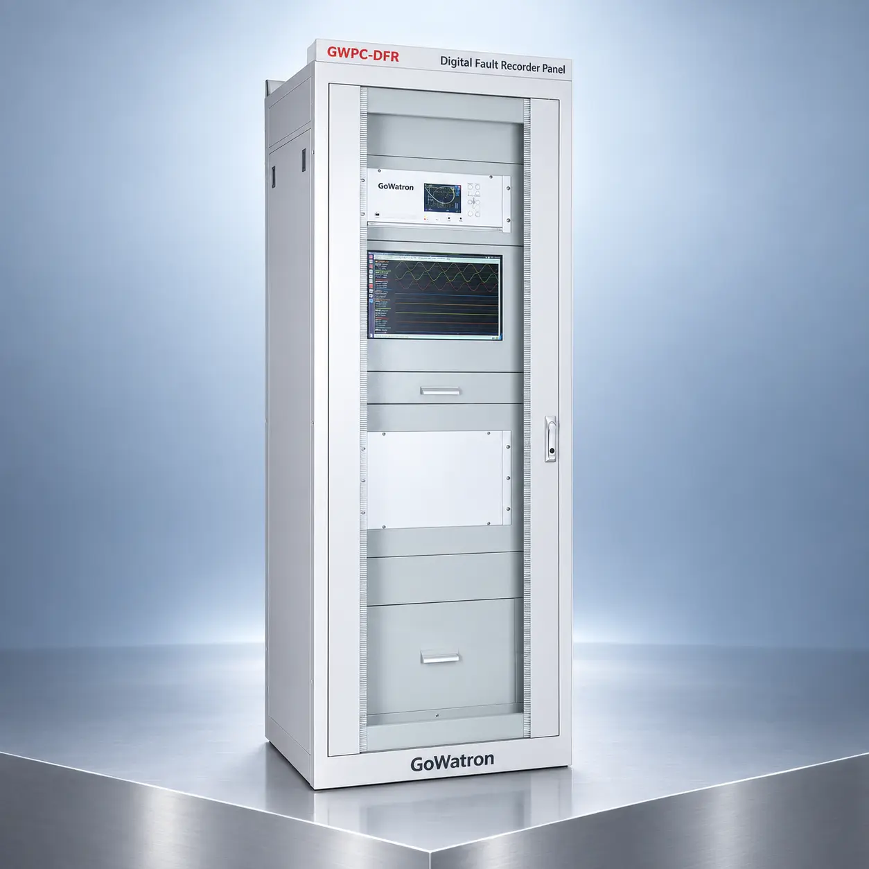
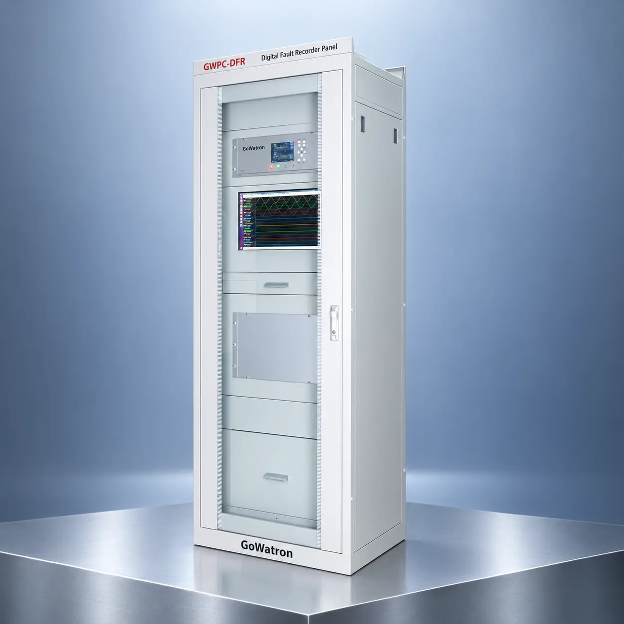
GWPC-DFR Digital Fault Recorder Panel
- The GWPC-DFR Digital Fault Recorder Panel is designed for power plants, substations, renewable energy facilities, and industrial power systems. It continuously monitors and records electrical quantities, equipment status signals, and protection events before, during, and after power system faults and disturbances.
- By integrating transient fault recording, continuous disturbance recording, sequence-of-events recording, fault analysis, and time synchronisation, the GWPC-DFR provides reliable data for reconstructing the chronology of disturbance events, analysing protection performance, locating faults, and evaluating the dynamic and operational performance of the power system.
- The GWPC-DFR is primarily a monitoring, recording, and analysis system. It does not replace protection relays and is not normally used to issue protection trip commands.




1. Product Description
The GWPC-DFR continuously acquires analogue quantities and binary status signals from primary equipment, instrument transformers, protection and control devices, and station service power systems.
Typical input signals include:
- AC currents and voltages from current transformers and voltage transformers;
- DC transducer output signals;
- Circuit-breaker and disconnector positions;
- Protection pickup, trip, and alarm signals;
- Automatic reclosing and breaker-failure protection signals;
- Generator, transformer, busbar, and feeder operating signals;
- Signals from station service power systems;
- Status signals from panel auxiliary components.
When a configurable trigger condition is detected, the system automatically stores the electrical waveforms, binary status changes, and event data recorded before and after the disturbance.
The recorded data enables engineers to determine:
- Where and when the fault occurred;
- How the disturbance developed;
- Whether the protection and control devices operated correctly;
- Whether the circuit breakers cleared the fault within the required time;
- Whether protection maloperation or failure to operate occurred;
- Whether abnormal oscillations, frequency deviations, or voltage disturbances were present.
The GWPC-DFR can be supplied as a stand-alone recorder panel or integrated into a substation automation system, SCADA system, or centralised disturbance-data management platform.
2. Main Functions
2.1 Transient Fault Recording
The GWPC-DFR records high-resolution current, voltage, frequency, and binary signals when a power system fault, abnormal operating condition, or switching event occurs.
Recording can be triggered by:
- Current or voltage threshold crossing;
- Sudden changes in current or voltage;
- Frequency deviation;
- Rate of change of frequency (ROCOF);
- Zero-sequence or negative-sequence quantities;
- Protection pickup or trip signals;
- Circuit-breaker operation;
- External binary inputs;
- Manual or remote commands.
Configurable pre-trigger and post-trigger recording periods allow the complete fault and disturbance sequence to be captured.
2.2 Continuous Disturbance Recording
The system can continuously record selected electrical quantities at a lower sampling rate over an extended period.
This function supports the analysis of:
- Power oscillations;
- Voltage and frequency variations;
- Generator and grid dynamic behaviour;
- Transformer overexcitation;
- System separation and load shedding;
- Renewable energy integration;
- Long-duration or slowly developing disturbances.
2.3 Sequence-of-Events Recording
Changes in binary input status are time-stamped and stored chronologically as sequence-of-events (SOE) records.
Typical recorded events include:
- Protection pickup and trip;
- Circuit-breaker opening and closing;
- Disconnector position changes;
- Automatic reclosing;
- Breaker-failure protection operation;
- Alarm activation and reset;
- Control command execution;
- Communication and device-status changes.
Accurate time synchronisation allows events recorded by different devices or at different substations to be correlated.
2.4 Fault Location and Analysis
Based on the recorded current and voltage quantities, the analysis software can calculate or assist in determining:
- Fault type;
- Faulted phase;
- Fault inception time;
- Fault clearing time;
- Fault duration;
- Fault current and voltage;
- Measured impedance;
- Estimated fault location;
- Circuit-breaker operating time;
- Protection operating sequence.
Fault-location accuracy depends on line parameters, measurement accuracy, fault resistance, network configuration, instrument-transformer performance, and the selected calculation method.
2.5 Power-Quality and Disturbance Analysis
Depending on the selected configuration, the GWPC-DFR can monitor and analyse:
- RMS current and voltage;
- Frequency and ROCOF;
- Active, reactive, and apparent power;
- Power factor;
- Harmonics and waveform distortion;
- Voltage dips, swells, and interruptions;
- Voltage and current unbalance;
- Power oscillations and abnormal trends.
Power-quality assessment and standards-compliance capabilities depend on the selected hardware, software, measurement methods, and applicable standards.
2.6 Automatic Report Generation
Following a fault or disturbance, the system can automatically generate reports containing:
- Fault occurrence time;
- Fault type and faulted phase;
- Fault duration;
- Maximum fault current;
- Minimum recorded voltage;
- Protection and circuit-breaker operating sequence;
- Estimated fault location;
- Analogue waveforms;
- Binary event records;
- SOE data.
Reports and waveform records can be viewed locally or accessed remotely by authorised users.
2.7 COMTRADE File Management
- Fault and disturbance records can be exported in the Common Format for Transient Data Exchange (COMTRADE) for data exchange and analysis using compatible third-party software.
- Support for a specific edition of IEEE/IEC 60255-24 must be confirmed for the selected system configuration.
2.8 Communication and System Integration
The GWPC-DFR supports the following communication protocols:
- IEC 61850;
- IEC 60870-5-104;
- IEC 60870-5-103;
- Modbus TCP;
- Modbus RTU.
- These protocols enable the recorder to exchange operating data, event information, and recording files with substation automation systems, SCADA systems, and centralised disturbance-data management platforms.
- For process-bus applications, the GWPC-DFR can be configured to receive IEC 61850-9-2 Sampled Values (SV).
- Compatibility with the required IEC 61850 edition, SV implementation profile, sampling rate, communication architecture, and time-synchronisation method must be verified during project engineering.
2.9 Configuration and Maintenance
The GWPC-DFR provides the following configuration and maintenance functions:
- Analogue- and binary-channel configuration;
- Trigger-threshold configuration;
- Recording-duration settings;
- Multiple setting-group management;
- User and access-right management;
- Event and operation logs;
- Device self-diagnostics;
- Communication-status monitoring;
- Analogue-channel zero-offset correction;
- Configuration backup and restoration;
- Import of Substation Configuration Description (SCD) files, where applicable.
3. Operating Principle
- The GWPC-DFR acquires analogue signals from current transformers, voltage transformers, and DC transducers, together with binary status signals from protection devices, control equipment, and primary apparatus.
- The recorder continuously processes the acquired signals and retains recent data in a circular buffer. When a configured trigger condition is detected, it preserves the specified pre-trigger data and continues recording for the configured post-trigger period.
The operating process comprises the following stages:
3.1 Signal Acquisition
- Currents, voltages, DC transducer output signals, and binary status signals are continuously acquired through the configured input channels.
- For digital-substation applications, the recorder may receive IEC 61850-9-2 Sampled Values, subject to the selected system configuration.
3.2 Signal Processing
The recorder processes the acquired data and calculates quantities such as:
- RMS current and voltage;
- Frequency;
- ROCOF;
- Positive-, negative-, and zero-sequence components;
- Active, reactive, and apparent power;
- Power factor;
- Measured impedance.
3.3 Trigger Detection
- Configured thresholds, sudden signal changes, protection events, binary inputs, or manual and remote commands can initiate recording.
3.4 Data Storage
- The recorder stores pre-trigger, fault-period, and post-trigger data as a complete fault or disturbance record.
3.5 Time Correlation
- Waveforms, status changes, and event data are time-stamped using the configured time-synchronisation source, allowing records from multiple devices to be correlated.
3.6 Fault Analysis
- The analysis software processes the recorded data to determine the fault type, faulted phase, operating sequence, fault-clearing time, circuit-breaker operating performance, and estimated fault location.
3.7 Reporting and Data Transmission
- The system generates fault reports and COMTRADE files and makes them available to authorised local and remote users.
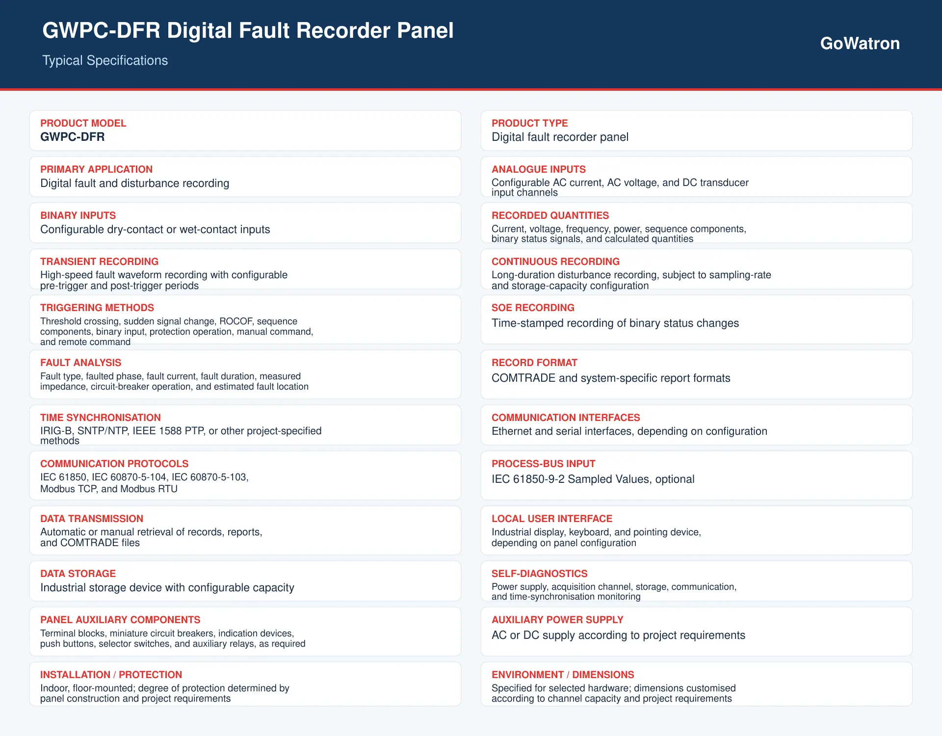
4. Basic Specifications
The following parameters represent typical system capabilities. Final specifications depend on the selected recorder, channel capacity, software functions, and project configuration.
5. Applications
The GWPC-DFR Digital Fault Recorder Panel is suitable for:
- Transmission substations;
- Distribution substations;
- Conventional power plants;
- Hydroelectric power plants;
- Wind and photovoltaic power plants;
- Energy-storage power stations;
- Generators and generator-transformer units;
- Main power transformers;
- Transmission lines;
- Distribution feeders;
- Busbar systems;
- Station service power systems;
- Industrial power distribution systems;
- Railway traction power systems;
- Centralised fault and disturbance recording systems.
The GWPC-DFR provides dependable fault and disturbance data for post-event analysis, protection-performance evaluation, fault-location assessment, equipment-condition investigation, and power system operation and maintenance.


