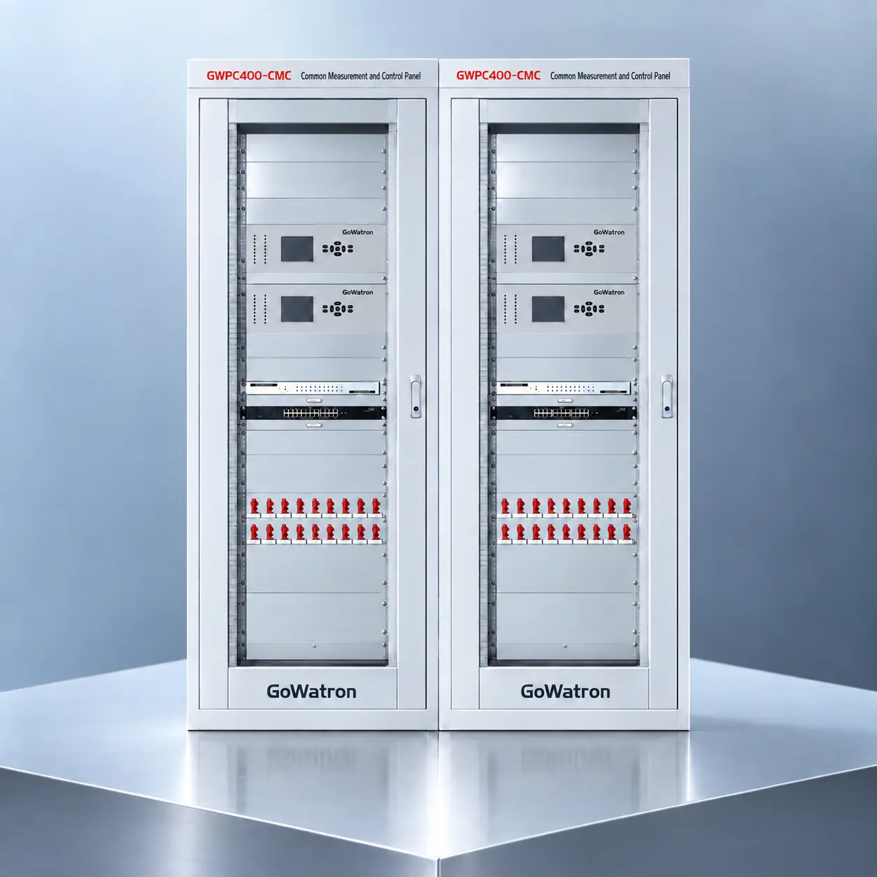
GWPC400-CMC Station Common Measurement and Control Panel
- The GWPC400-CMC Station Common Measurement and Control Panel is designed for station-wide common signal acquisition, busbar voltage supervision, equipment status monitoring and remote control in substations, power plants and renewable energy facilities.
- Built around the GWPR400-CMC Common Measurement and Control Unit, the panel serves as an interface between primary equipment, station auxiliary systems and the substation automation system or SCADA platform. It collects analogue measurements, binary status signals and alarm indications while providing supervised control and remote regulation functions for designated station equipment.
- The GWPC400-CMC is suitable for both conventional and digital substation applications. It can be configured for projects at voltage levels such as 132 kV, 66 kV and 33 kV, as well as other voltage levels subject to project requirements.




1. Product Description
1.1 GWPR400-CMC Common Measurement and Control Unit
- The panel is built around the GWPR400-CMC Common Measurement and Control Unit, which is designed to acquire and process station-wide common signals and auxiliary-system information.
- Based on a unified hardware and software platform, the unit supports analogue measurement, binary input acquisition, event recording, remote control and communication with the substation automation system.
- Depending on the selected hardware and firmware configuration, the unit supports IEC 61850 and IEC 60870-5-103 communication.
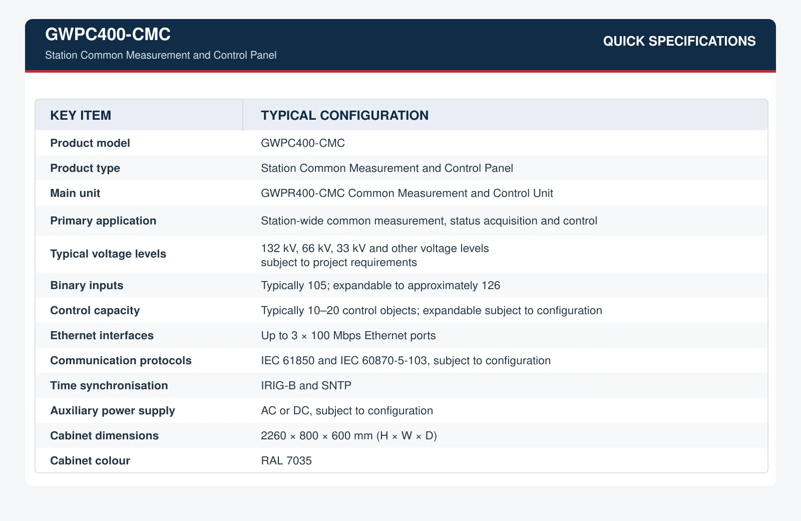
1.2 Quick Specifications
1.3 Hardware Design
The GWPR400-CMC incorporates a high-performance 32-bit dual-core processor. Its dual-channel sampling and cross-checking architecture improves measurement reliability and helps identify abnormal sampling conditions.
The unit features:
- A robust front panel and fully enclosed chassis;
- Physical separation between power-supply, measurement and control circuits;
- EMC-oriented hardware and PCB design;
- Up to three 100 Mbps Ethernet interfaces;
- One RS-232 interface for printer or engineering applications;
- IRIG-B and SNTP time-synchronisation options;
- AC or DC auxiliary power-supply options.
These features make the unit suitable for electrically demanding substation and power-plant environments.
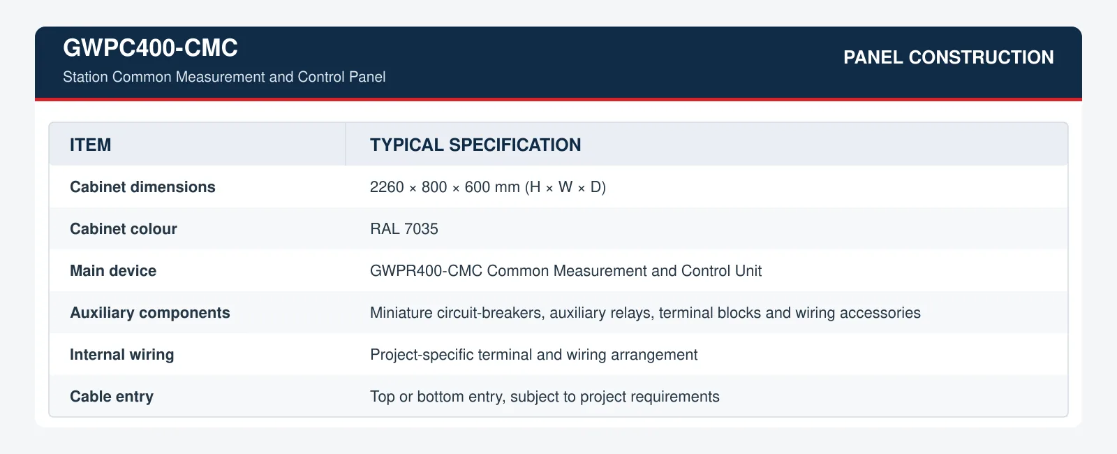
1.4 Panel Construction
The panel is normally installed in a standard floor-standing cabinet and supplied with the necessary auxiliary components, terminal blocks and internal wiring.
2. Main Functions
The GWPC400-CMC provides the principal SCADA functions of telemetry, status indication, remote control and remote regulation.
2.1 Telemetry and Analogue Measurement
The panel can acquire and calculate station-wide electrical quantities, including:
- Busbar phase-to-neutral voltages;
- Busbar phase-to-phase voltages;
- Zero-sequence voltage;
- System frequency;
- Positive-, negative- and zero-sequence voltage components;
- Station service transformer currents;
- Active power, reactive power and power factor;
- 380/400 V AC auxiliary-system voltages and currents;
- DC system analogue measurements;
- Main transformer oil and winding temperatures;
- Other non-electrical quantities provided through analogue transducers.
The actual measurement quantities depend on the selected analogue input modules and project-specific configuration.
2.2 Status Indication and Alarm Acquisition
The panel acquires binary status and alarm signals from primary equipment, protection devices and station auxiliary systems.
Typical signals include:
- Circuit-breaker positions;
- Disconnector positions;
- Earthing-switch positions;
- Local/remote selector-switch status;
- Remote-control enable and blocking signals;
- Protection trip and alarm signals;
- OLTC tap-position indications;
- DC power-supply system alarms;
- UPS and inverter status signals;
- Fire-alarm system indications;
- Earth-fault monitoring system alarms;
- VT ferroresonance suppression device status;
- GPS, BeiDou or other station clock status;
- Communication and device self-supervision alarms.
A typical configuration provides 105 binary inputs and can be expanded to approximately 126 binary inputs, subject to the selected hardware configuration.
2.3 Remote Control
The panel supports supervised remote control of designated primary and auxiliary equipment, including:
- Opening and closing VT disconnectors;
- Controlling 380/400 V AC auxiliary incomer circuit-breakers;
- Controlling auxiliary-system bus-section circuit-breakers;
- Controlling selected station service equipment;
- Executing project-specific control sequences.
Control commands are subject to control-authority verification, select-before-operate procedures, equipment status checks and project-specific electrical interlocking conditions.
A typical panel can be configured for approximately 10–20 control objects. The control capacity can be expanded according to the required number of control outputs, feedback signals and interlocking conditions.
2.4 Remote Regulation
Where required by the project, the panel can provide remote regulation and raise/lower control functions, including:
- OLTC tap raise and tap lower commands;
- Manual or automatic voltage-regulation commands;
- Generator output adjustment;
- Other project-specific set-point or regulation commands.
The availability of these functions depends on the external equipment interfaces and the approved station control philosophy.
2.5 VT Secondary-Circuit Paralleling
- For substations with sectionalised or double-busbar arrangements, the GWPC400-CMC can provide supervised VT secondary-circuit paralleling.
- When the bus-coupler or bus-section circuit-breaker is closed and all predefined permissive conditions are satisfied, the VT secondary circuits associated with the relevant bus sections can be paralleled to provide a common voltage reference.
- The paralleling operation is subject to electrical interlocking, VT disconnector status, secondary-circuit isolation status and other project-defined safety conditions.
2.6 VT Secondary-Voltage Transfer
- When the VT associated with one bus section is isolated or unavailable, the panel can transfer the voltage reference to an available VT associated with another energised bus section.
- This function maintains voltage-input continuity for measurement, protection, synchronising and automation systems. Automatic or manual transfer can be provided according to the approved station operating logic.
- The transfer is executed only after the required circuit-breaker, disconnector, VT isolation and interlocking conditions have been verified.
3. Communication and Time Synchronisation
The GWPC400-CMC can be integrated into conventional or IEC 61850-based substation automation architectures.
Typical communication and time-synchronisation options include:
- IEC 61850 station-bus communication;
- IEC 60870-5-103 communication;
- Up to three 100 Mbps Ethernet interfaces;
- One RS-232 interface for printer or engineering applications;
- IRIG-B time synchronisation;
- SNTP network time synchronisation.
The Ethernet ports can be assigned to station-bus communication, engineering access or separate communication networks, subject to the selected hardware and system architecture.
The available protocols, interfaces and network arrangements depend on the selected device version, firmware and project configuration.
4. Typical Applications
- Substations;Centralised acquisition of busbar voltages, equipment status, common alarms and auxiliary-system measurements in substations at voltage levels such as 132 kV, 66 kV and 33 kV.
- Double-Busbar Substations;Centralised monitoring and control in double-busbar substations requiring supervised VT secondary-circuit paralleling and voltage transfer.
- Sectionalised Single-Busbar and Bridge Configurations;Monitoring of incomer, bus-section and bus-coupler conditions and provision of common voltage and status information for station automation functions.
- Power Plants;Acquisition of common electrical and non-electrical signals from station auxiliary systems, together with supervised control of designated auxiliary equipment.
- Solar and Wind Power Plants;Monitoring of step-up substation busbar voltages, station service systems, inverter or converter status, transformer signals and other common plant information.
- Substation Automation Retrofit Projects;Replacement of legacy measurement, control or remote terminal equipment while retaining conventional hardwired interfaces or integrating the station into an IEC 61850-based automation system.
- International EPC Projects;Project-specific measurement, control and communication solutions for substations using IEC-based automation architectures and voltage classes such as 132 kV, 66 kV and 33 kV.
5. Key Benefits
- Centralised acquisition of station-wide common signals;
- Accurate busbar voltage measurement and supervision;
- Supervised VT secondary-circuit paralleling and voltage transfer;
- Flexible I/O configuration with expandable binary inputs and control outputs;
- IEC 61850 and conventional communication options;
- IRIG-B and SNTP time synchronisation;
- Electrical interlocking and anti-maloperation logic;
- Customisable cabinet, terminal and communication configuration;
- Suitable for new substations and automation retrofit projects.


