Transformer Differential Protection (ANSI 87T): Operating Principle, Functions and Setting Calculations
Transformer differential protection (ANSI 87T) is one of the main electrical protection schemes for power transformers. It compares the vector sum of the currents from all transformer sides after magnitude matching and phase compensation to detect faults within the protected zone. During normal operation or external faults, the compensated currents are approximately balanced and the differential current remains small. For an internal fault, the protection trips the associated circuit breakers when the differential current satisfies the operating characteristic and no applicable blocking condition is present.
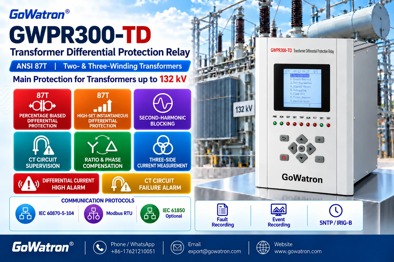
The GoWatron GWPR300-TD Transformer Differential Protection Relay is designed for two-winding and three-winding power transformers rated at 110 kV and below, as specified in this edition of the manual. It supports differential protection with current inputs from up to three transformer sides and provides unrestrained high-set differential protection, percentage-restrained differential protection, CT circuit failure alarm and differential current alarm.
1. Operating Principle of Transformer Differential Protection
1.1 Current Magnitude Matching and Phase Compensation
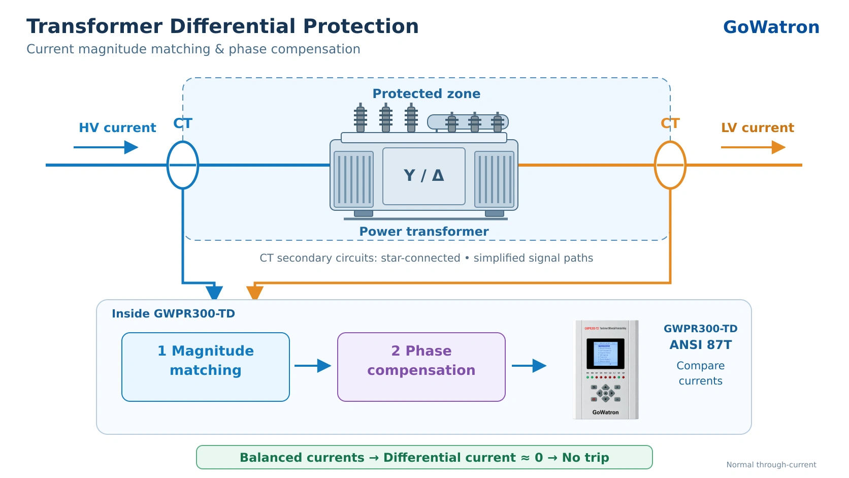
- The rated currents on different transformer sides are generally unequal, and the winding vector group may introduce a phase displacement. The CT secondary currents therefore cannot be compared directly.
- The GWPR300-TD uses the transformer rated power, rated voltage of each winding, CT ratios and winding connections to perform current magnitude matching and automatic phase compensation. This places the currents used in the differential calculation on a common reference basis.
- The relay requires the CT secondary circuits on all transformer sides to be star-connected, with phase compensation performed in software. Where Y-to-Δ compensation is required, the relay uses phase-to-phase current differences. This also removes the zero-sequence component from the compensated currents on that side. External interposing CTs are therefore generally unnecessary for magnitude matching and phase compensation.
- The matching coefficient must not be assumed to be permanently equal to 1 on the HV side. According to this edition of the manual, the HV-side coefficient is \( 1/\sqrt{3} \) for a star-connected HV winding and 1 for a delta-connected HV winding. The coefficients for the other sides also depend on their rated voltages, CT ratios and winding connections.
1.2 Differential Current and Restraint Current
For a three-winding transformer, the differential current for each phase is:
\[ I_{\mathrm d}= \left| \dot I’_{\mathrm h}+ \dot I’_{\mathrm m}+ \dot I’_{\mathrm l} \right| \]
The restraint current is the maximum magnitude of the corresponding compensated phase currents:
\[ I_{\mathrm r}= \max\left( |\dot I’_{\mathrm h}|, |\dot I’_{\mathrm m}|, |\dot I’_{\mathrm l}| \right) \]
where:
- \( \dot I’_{\mathrm h} \): compensated phase-current phasor on the HV side;
- \( \dot I’_{\mathrm m} \): compensated phase-current phasor on the MV side;
- \( \dot I’_{\mathrm l} \): compensated phase-current phasor on the LV side.
For a two-winding transformer, only the currents from the two connected sides are included.
During an external fault, the restraint current increases with the through-fault current. This improves stability against spill current caused by CT errors and CT saturation. Transformer differential protection settings and tests must use the relay’s maximum-current restraint definition; slope settings from other restraint algorithms cannot be transferred directly.
1.3 Percentage-Restrained Differential Characteristic
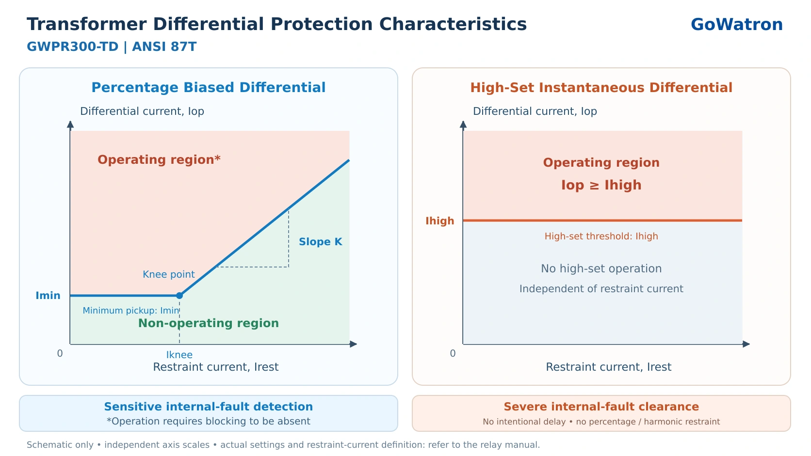
The GWPR300-TD uses a percentage-restrained differential characteristic consisting of a horizontal section and a sloping section.
When the restraint current does not exceed the breakpoint:
\[ I_{\mathrm r}\leq I_{\mathrm{gd}} \]
the current operating condition is:
\[ I_{\mathrm d}>I_{\mathrm{cdqd}} \]
When the restraint current exceeds the breakpoint:
\[ I_{\mathrm r}>I_{\mathrm{gd}} \]
the current operating condition is:
\[ I_{\mathrm d}-I_{\mathrm{cdqd}} \geq K_{\mathrm b}(I_{\mathrm r}-I_{\mathrm{gd}}) \]
where:
- \( I_{\mathrm{cdqd}} \): differential pickup current setting;
- \( I_{\mathrm{gd}} \): restraint-current breakpoint setting;
- \( K_{\mathrm b} \): percentage-restraint slope coefficient.
The percentage-restrained differential element must also be enabled, and any enabled second-harmonic blocking and CT circuit failure blocking conditions must permit operation. According to the manual, the corresponding phase’s high-set differential element must not have operated. Once the high-set element operates, the corresponding percentage-restrained element is prevented from operating additionally.
1.4 Second-Harmonic Blocking
Transformer energisation or voltage recovery may produce magnetising inrush current. Inrush current can appear as a large differential current, so transformer differential protection requires measures to distinguish it from an internal fault.
The GWPR300-TD uses a second-harmonic criterion applied to the differential current. With second-harmonic blocking enabled, the harmonic condition permitting percentage-restrained differential operation in the corresponding phase is:
\[ I_{\mathrm{d},2}
where:
- \( I_{\mathrm{d},2} \): magnitude of the second-harmonic component of that phase’s differential current;
- \( I_{\mathrm d} \): magnitude of the fundamental-frequency differential current used for operation;
- \( K_2 \): second-harmonic blocking ratio setting.
When the second-harmonic-to-fundamental ratio reaches or exceeds the setting, the corresponding phase’s percentage-restrained differential element is blocked. This function can be enabled or disabled through its protection control setting.
Some inrush conditions may have relatively low second-harmonic content. An empirical threshold alone cannot guarantee secure blocking under every condition; performance should be verified against the transformer characteristics and test results.
1.5 Unrestrained High-Set Differential Protection
The high-set differential element is an independent element intended to clear severe internal faults rapidly.
With the GWPR300-TD high-set differential element enabled, operation occurs without intentional time delay when the differential current in any phase satisfies:
\[ I_{\mathrm d}\geq I_{\mathrm{sd}} \]
The high-set differential logic in this edition of the manual does not include second-harmonic blocking or CT circuit failure blocking. Its setting must therefore account for magnetising inrush and false differential current caused by CT saturation during external faults.
1.6 CT Circuit Failure Detection and Alarm
The GWPR300-TD CT circuit failure logic includes initiating criteria, inhibiting criteria and phase-current loss detection criteria. A low current in one phase alone is insufficient to establish CT circuit failure
The detection logic is initiated by percentage-restrained differential pickup or by any phase differential current reaching half the differential pickup setting. Instantaneous CT circuit failure detection is inhibited if either of the following conditions applies:
- The maximum phase current after initiation exceeds \( 1.2 \)times the rated current of the relevant transformer side.
- A phase current on any side has increased compared with its value before initiation.
When the initiating criteria are satisfied and detection is not inhibited, CT circuit failure on a particular side is identified if one or two phase currents are below \(0.04I_{\mathrm n}\), while the remaining phase current or currents are above \(0.04I_{\mathrm n}\).
Here, \( I_{\mathrm n} \)is the rated CT secondary current on that side: 1 A or 5 A.
If CT circuit failure blocking is enabled, the percentage-restrained differential protection is blocked when the failure criteria are met. If the CT circuit failure alarm is enabled, an alarm is issued after a 10 s delay.
1.7 Differential Current Alarm
With the differential current alarm enabled, an alarm is issued when the following conditions persist for 3 s:
\[ I_{\mathrm d}\geq0.5I_{\mathrm{cdqd}} \]
in any phase, and neither the high-set nor the percentage-restrained differential protection has operated.
The alarm indicates sustained abnormal differential current. Checks should focus on the CT circuits, CT ratio settings, winding connection settings and compensation parameters. The alarm alone does not establish that an internal transformer fault is present.
2. Functions of Transformer Differential Protection
- The boundaries of the transformer differential protection zone are determined by the CT locations. The zone typically includes the transformer windings, bushings and connecting conductors located between the CTs.
2.1 Winding Phase-to-Phase Fault Protection
- A phase-to-phase winding fault disrupts the balance between the currents on the transformer sides. Transformer differential protection trips rapidly when its operating conditions are satisfied, helping to limit fault damage.
2.2 Internal Earth-Fault Protection
- Transformer differential protection can operate for internal earth faults that produce sufficient differential current. Its sensitivity depends on the neutral earthing arrangement, winding connections, fault location and fault resistance.
- Earth faults close to the neutral point may produce relatively small differential currents. Restricted earth-fault protection or other supplementary protection should therefore be provided where required by the application.
2.3 Interturn Fault Protection
- Transformer differential protection can operate when an interturn fault produces sufficient differential current at the winding terminals. An incipient interturn fault may involve a substantial circulating current within the shorted turns but only a small terminal differential current. Conventional overall differential protection therefore has limited sensitivity to such faults.
2.4 Bushing and Connection Fault Protection
- Bushing flashovers, short circuits in connecting conductors and other electrical faults within the differential zone can be cleared by transformer differential protection. External faults should be cleared by the relevant protection, while the differential protection remains stable.
- The GWPR300-TD can also accept non-electrical protection signals, including Buchholz, temperature, pressure-relief and oil-level signals, and initiate alarms or trips according to the configuration. These are complementary protection functions and do not form part of the differential-current operating criterion.
3. Transformer Differential Protection Setting Calculations
3.1 Rated Current and CT Secondary Current Conversion
The rated primary current on transformer side\( j \)is:
\[ I_{\mathrm N,j}= \frac{1000S_{\mathrm N}} {\sqrt{3}U_{\mathrm N,j}} \]
where\( S_{\mathrm N} \) is expressed in MVA and \( U_{\mathrm N,j} \) in kV. The resulting current is in amperes.
The corresponding rated current referred to the CT secondary is:
\[ I_{\mathrm e,j}= \frac{1000S_{\mathrm N}} {\sqrt{3}U_{\mathrm N,j}n_{\mathrm{CT},j}} \]
where:
\[ n_{\mathrm{CT},j}= \frac{I_{\mathrm{CT,pri},j}} {I_{\mathrm{CT,sec},j}} \]
\( I_{\mathrm e,j} \)is the transformer rated current on that side referred to the CT secondary. It must not be confused with the rated CT secondary current \( I_{\mathrm n} \).
Before setting the protection, enter the transformer rated power, rated voltage of each winding, CT primary and secondary ratings, and winding connection parameters correctly so that the relay can perform the required calculations.
3.2 Current Matching Coefficients
According to this edition of the manual, the matching coefficients referenced to the HV side are:
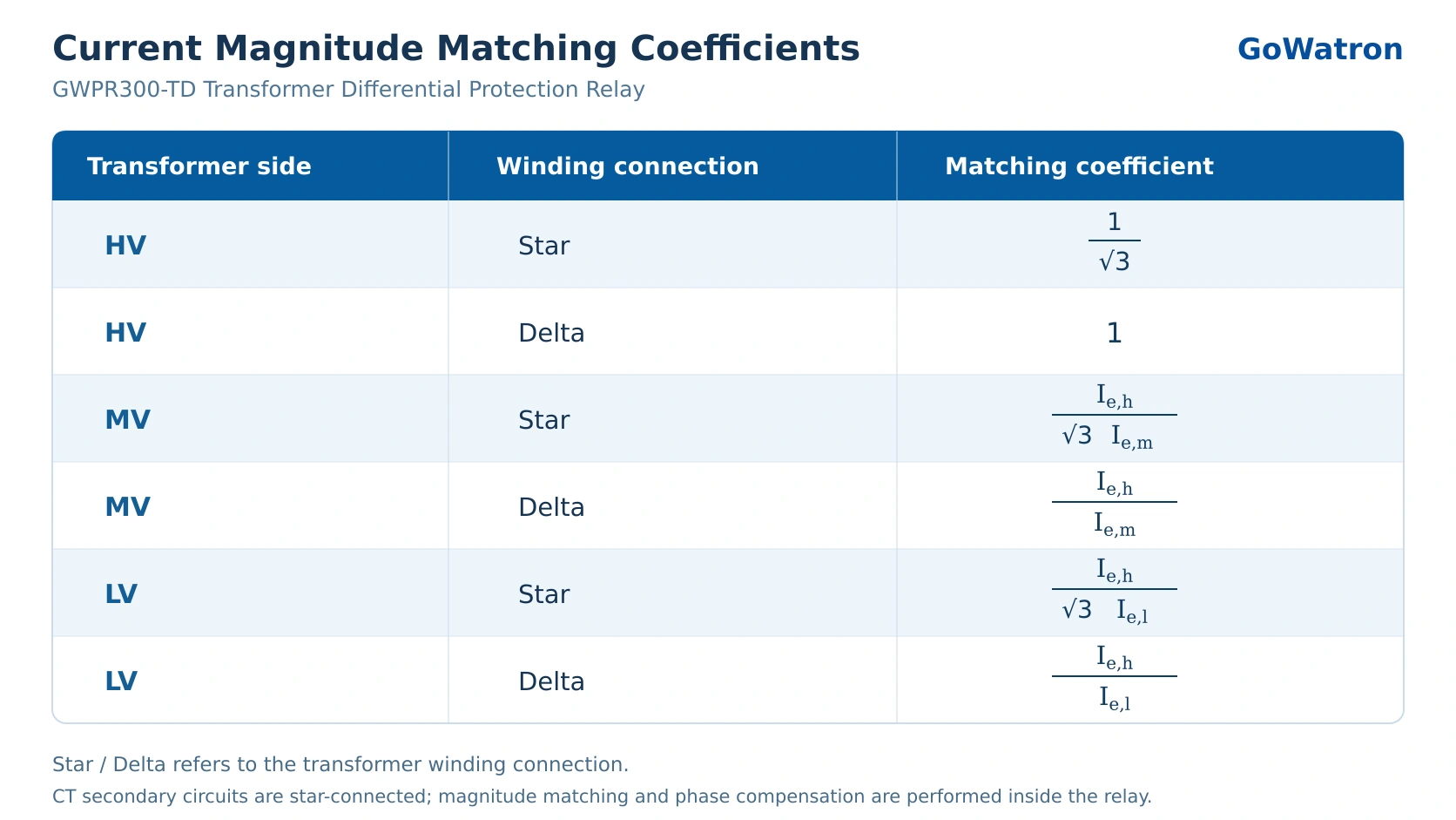
For star-connected windings, these coefficients must be used together with the software phase-to-phase current-difference compensation. They must not be applied independently of the phase-compensation equations.
3.3 Differential Pickup Current
The differential pickup setting must exceed the maximum differential current expected during normal operation, while maintaining adequate sensitivity to the minimum internal fault:
\[ I_{\mathrm{cdqd}} \geq K_{\mathrm{rel}}I_{\mathrm{unb,max}} \]
where:
- \( I_{\mathrm{unb,max}} \): maximum normal-operation spill current referred to the differential calculation basis;
- \( K_{\mathrm{rel}} \): security margin factor selected in accordance with the applicable setting procedure.
The calculation should account for CT errors, tap-position variation, compensation errors and excitation current. The site setting must not be selected solely from the default value or a fixed multiple of rated current.
3.4 Restraint-Current Breakpoint
- The breakpoint must be coordinated with the differential pickup setting and percentage-restraint slope.
- For the GWPR300-TD characteristic, with the other settings unchanged and the operating point in the sloping section, reducing the breakpoint raises the differential operating threshold at a given restraint current. Increasing the breakpoint lowers that threshold.
- An excessively low breakpoint may reduce sensitivity to some internal faults, while an excessively high breakpoint may reduce stability under some external-fault conditions. The setting should therefore be established from the relevant fault calculations.
3.5 Percentage-Restraint Slope
The slope must ensure that the differential operating threshold exceeds the spill current expected during external faults, with an appropriate margin.
For an external-fault condition where\( I_{\mathrm{r,ext}}>I_{\mathrm{gd}} \), the following check can be applied:
\[ I_{\mathrm{cdqd}}+ K_{\mathrm b}(I_{\mathrm{r,ext}}-I_{\mathrm{gd}}) > K_{\mathrm{rel}}I_{\mathrm{d,ext}} \]
where\( I_{\mathrm{d,ext}} \) is the estimated false differential current under the external-fault condition being assessed.
The assessment should consider maximum through-fault current, transient CT saturation, differences between CT characteristics and transformer tap-position variation. Internal-fault sensitivity must be checked again after increasing the slope.
3.6 Second-Harmonic Blocking Ratio
The second-harmonic blocking setting must balance security during magnetising inrush against dependable operation for internal faults.
An excessively low threshold can increase the risk of unwanted blocking during internal faults. An excessively high threshold can reduce blocking security during inrush.
The GWPR300-TD setting range is 0.05–0.5, with a default of 0.2. For inrush conditions with low second-harmonic content, blocking performance should be assessed using relevant disturbance records and tests. Lowering the threshold alone may not resolve the issue, and waveform-recognition functions not listed in the manual must not be assumed to be available.
3.7 High-Set Differential Current
The GWPR300-TD high-set differential element does not use the second-harmonic blocking criterion. Its setting must exceed the maximum relevant inrush differential current and false differential current caused by CT saturation during external faults:
\[ I_{\mathrm{sd}}> K_{\mathrm{rel}} \max\left( I_{\mathrm{inrush,max}}, I_{\mathrm{d,ext,max}} \right) \]
where:
- \( I_{\mathrm{inrush,max}} \): maximum fundamental-frequency RMS differential current during transformer energisation or other relevant inrush conditions, evaluated using the relay’s measurement algorithm and referred to the differential calculation basis;
- \( I_{\mathrm{d,ext,max}} \): maximum false differential current during external faults, evaluated using the same algorithm and reference basis.
The instantaneous peak of an inrush waveform must not be compared directly with a fundamental-frequency RMS current setting. The high-set element must also be checked for adequate sensitivity to the severe internal faults it is intended to clear.
3.8 Sensitivity Verification
For the minimum internal-fault condition, calculate the compensated differential and restraint currents and compare them with the corresponding operating threshold.
In the horizontal section, verify:
\[ I_{\mathrm{d,min}}>I_{\mathrm{cdqd}} \]
In the sloping section, verify:
\[ I_{\mathrm{d,min}}-I_{\mathrm{cdqd}} \geq K_{\mathrm b}(I_{\mathrm{r,int}}-I_{\mathrm{gd}}) \]
These inequalities establish entry into the operating region only. The application must also satisfy the sensitivity margin required by the applicable setting procedure.
Where a sensitivity factor is used, its definition and acceptance value must follow the relevant procedure. A requirement of \(K_{\mathrm{sen}}\geq2\) must not be treated as universal. Sensitivity must also not be assessed solely by dividing the minimum fault differential current by the pickup setting, without accounting for restraint during the fault.
3.9 GWPR300-TD Differential Protection Settings
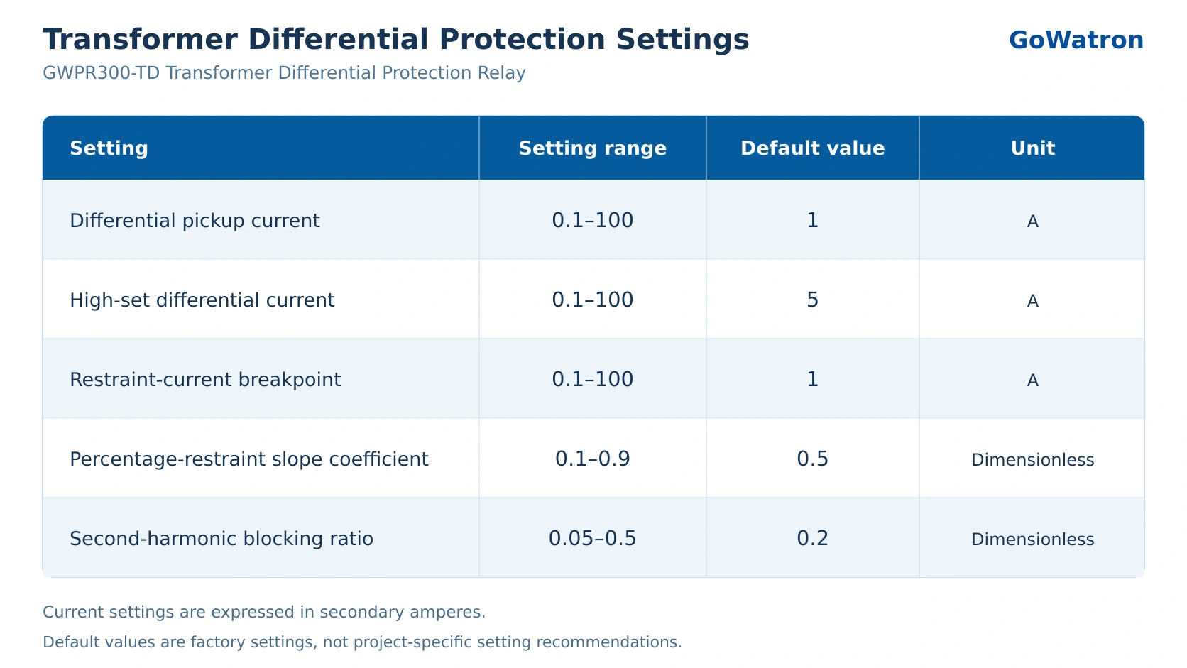
The current settings apply to the relay’s differential calculations and must be interpreted in conjunction with the CT ratios and compensation basis. They must not be treated directly as primary-current values. Default values are not recommended site operating settings.
4. Application and Commissioning Considerations
4.1 Verify Transformer and CT Parameters
- Before commissioning transformer differential protection, verify the rated power, rated voltages, winding connections, CT ratios, CT polarities and phase sequence.
- This edition of the manual requires star-connected CT secondary circuits. CT polarity must follow the manual and approved project wiring diagrams; a current-direction convention used in calculations does not replace physical wiring checks.
4.2 Distinguish Transformer Rated Current from CT Rated Secondary Current
- \( I_{\mathrm e} \) is the transformer rated current referred to the CT secondary, whereas \( I_{\mathrm n} \) is the rated CT secondary current. They are used in different criteria and must not be interchanged.
- This edition of the manual does not list “rated current, 0.1–100 A, default 5 A” as an independent protection setting.
4.3 Verify Protection and Blocking Enable Settings
- Enable or disable the high-set differential element, percentage-restrained differential element, second-harmonic blocking, CT circuit failure blocking and alarm functions in accordance with the approved protection scheme.
- CT circuit failure blocking and CT circuit failure alarm have separate enable settings and must be checked individually. Enabling the alarm does not automatically enable blocking.
4.4 Test Using the Relay’s Actual Algorithm
- Transformer differential protection tests must account for the matching coefficients, phase compensation and maximum-current restraint algorithm. Verify the horizontal and sloping sections, high-set differential operation and second-harmonic blocking separately.
- If the injected test-current combination activates CT circuit failure blocking, the blocking function may be temporarily disabled in accordance with the approved test procedure. Restore and verify the operating configuration after testing.
4.5 Save Settings and Complete Commissioning Checks
- According to this edition of the manual, enter password 1000 when exiting the relevant setting screen to save changes to protection settings and control words. Confirm that the correct setting group is active.
- Before energisation, complete setting verification, protection characteristic tests, blocking-logic tests and trip-circuit functional tests. Once suitable load conditions are available, verify the current magnitudes, phase relationships and differential currents.


