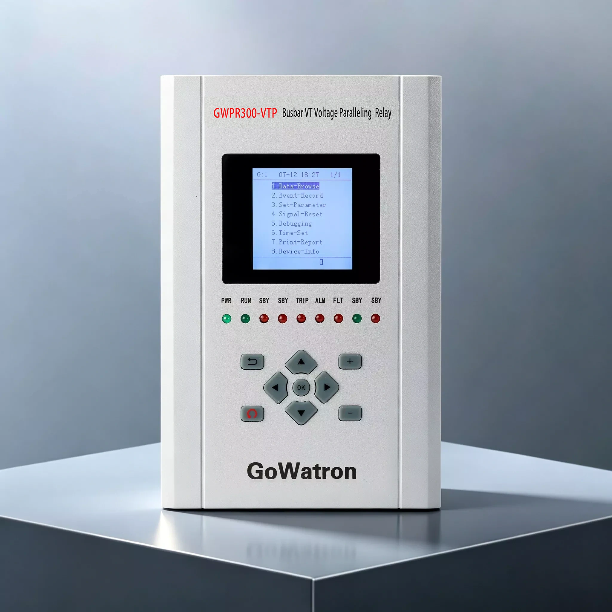
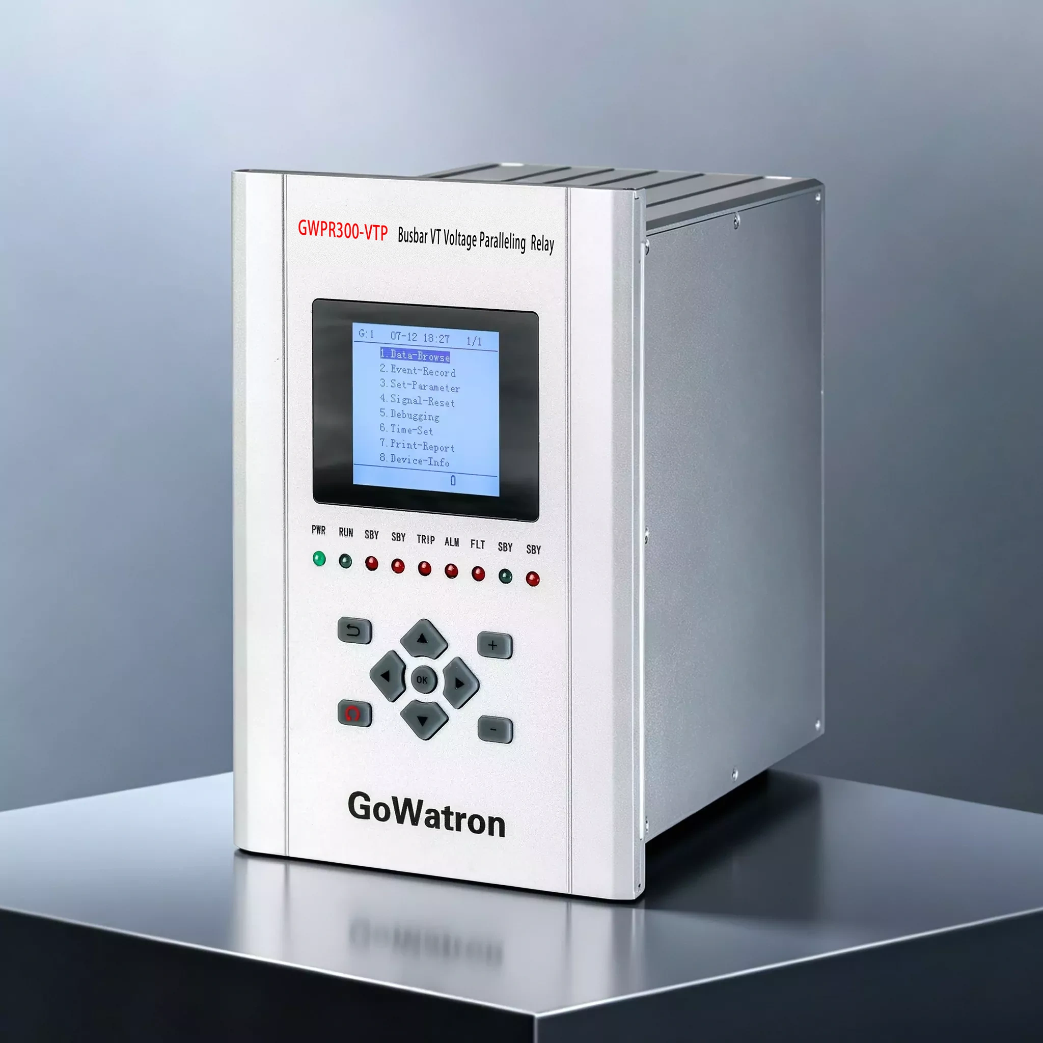
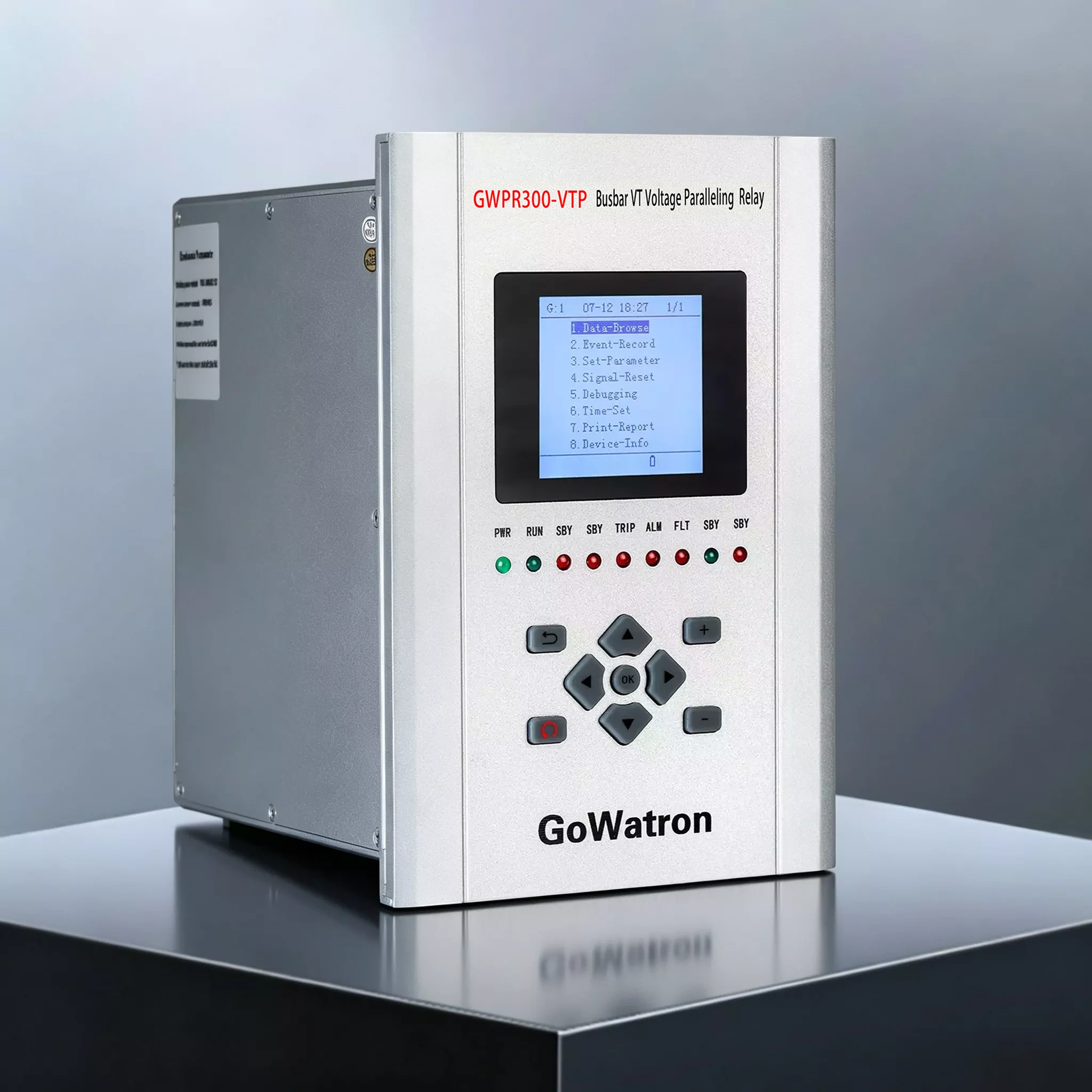



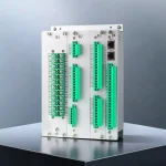
GWPR300-VIP Busbar VT Voltage Paralleling Relay
The GoWatron GWPR300-VTP Busbar VT Paralleling Relay integrates voltage monitoring, abnormal voltage alarms and VT secondary voltage circuit paralleling and de-paralleling. It continuously monitors the voltages of two busbar sections and automatically establishes the secondary paralleling connections when the primary busbar paralleling status, paralleling permissive signal and relevant voltage criteria are satisfied. It also provides overvoltage, undervoltage and residual overvoltage alarms.
Communication:
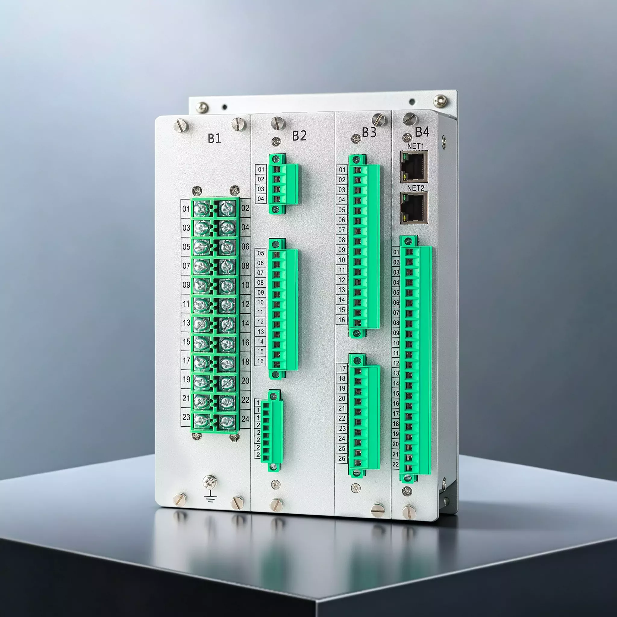
• Two Ethernet ports supporting IEC 60870-5-104;
• Two optional Ethernet ports supporting IEC 61850;
• One RS-485 communication port supporting Modbus RTU.




1.Product Introduction
- The GWPR300-VTP is a Busbar VT Paralleling Relay designed for voltage transformer (VT) secondary circuits associated with two busbar sections. It measures busbar voltages, frequency and metering-circuit voltages, and provides VT paralleling control, event recording, disturbance recording and communication with supervisory systems.
- The relay features a local human–machine interface for parameter configuration, status viewing and on-site testing. It can be integrated into a substation automation system or a supervisory control and data acquisition (SCADA) system for centralised monitoring and operational management.
2. Product Functions
Protection and alarm functions:
- (ANSI 59) Overvoltage alarm;
- (ANSI 27) Undervoltage alarm;
- (ANSI 59N) Residual overvoltage alarm.
- Busbar VT Paralleling
The relay provides separate voltage alarm functions for Busbar Sections I and II. Each function can be individually enabled or disabled.
- VT paralleling control: Provides automatic paralleling and de-paralleling of VT secondary voltage circuits according to the primary busbar paralleling status, paralleling permissive signal and relevant voltage criteria. Measurement and control: Measures phase-to-neutral voltages, phase-to-phase voltages, residual voltages and metering-circuit voltages for both busbar sections, together with frequencies F1 and F2. Provides 21 powered (wet-type) binary inputs, 15 independent relay outputs and one device power-failure alarm output. Binary input voltage options are 220 V AC/DC, 110 V DC or 48 V DC and must be specified when ordering.
Communication:
- Two Ethernet ports supporting IEC 60870-5-104;
- Two optional Ethernet ports supporting IEC 61850;
- One RS-485 communication port supporting Modbus RTU.
Time synchronisation: Supports time synchronisation via communication protocols, SNTP and IRIG-B.
Printing: Supports a dot-matrix printer with a serial interface for printing settings, event records and disturbance records.
Recording: Stores up to 128 records each for protection events, alarm events, binary input status changes and operator actions; 32 self-diagnostic event records; and 32 disturbance records. Each disturbance record contains 10 cycles, comprising four pre-trigger cycles and six post-trigger cycles.
3. Main Technical Specifications
- Operating environment: Operating temperature −40 to +70 °C; relative humidity 5% to 90%, non-condensing.
- Auxiliary power supply and power consumption: 100–264 V AC or 100–264 V DC; AC supply frequency 50 Hz ±0.5 Hz; AC supply total harmonic distortion ≤15%; DC supply ripple ≤5%. With a DC auxiliary supply, power consumption is ≤10 W during normal operation and ≤15 W during protection operation. The burden of each AC voltage input circuit is ≤0.5 VA per phase.
- AC voltage inputs: Rated secondary input voltage 100 V; frequency measurement range 35–65 Hz. The voltage input circuits can withstand 1.4 times the rated voltage continuously.
- Measurement accuracy: Voltage accuracy class 0.2; frequency measurement error ±0.01 Hz; frequency setting error within ±0.02 Hz; binary input time resolution ≤1 ms.
- Relay outputs: Potential-free contacts rated at 8 A at 250 V AC and 8 A at 30 V DC. Output relay operating time ≤8 ms; release time ≤5 ms.
- Protection settings: Overvoltage setting range 1–600 V, default 120 V; undervoltage setting range 30–400 V, default 80 V; residual overvoltage setting range 1–400 V, default 30 V. The corresponding time delays are adjustable from 0.05 to 100 s. These setting ranges do not represent the permissible continuous input voltage range. Actual settings must be determined according to the VT configuration and operating requirements.
- VT paralleling conditions: The VT paralleling function must be enabled, with B405 (primary busbar paralleling status) = 1 and B406 (paralleling permissive) = 1. All three phase-to-phase voltages on the source side must exceed 0.3Un, while all three phase-to-phase voltages on the other side must be below 0.3Un. When all conditions are satisfied, the Busbar VT Paralleling Relay operates the corresponding paralleling relays, illuminates the front-panel “Paralleling” indicator and displays “Section I VT Paralleling” or “Section II VT Paralleling”. Un is the rated VT secondary voltage configured in the device parameters.
- VT de-paralleling: The corresponding paralleling relays release, removing the secondary paralleling connections, if the source-side voltage is lost, the VT voltage on the other side is restored, or either the primary busbar paralleling status signal or the paralleling permissive signal is withdrawn.
4. Applications
- The GWPR300-VTP Busbar VT Paralleling Relay is suitable for substations, power plants and industrial power distribution systems requiring voltage monitoring, abnormal voltage alarms and controlled paralleling of VT secondary voltage circuits. It can be installed in protection and control panels or locally in switchgear.


