GWDT-MS Distributed Temperature Sensing System (DTS)
- The GWDT-MS Distributed Temperature Sensing System (DTS), developed and manufactured by GoWatron, is an online temperature monitoring system. Based on Raman scattering and Optical Time-Domain Reflectometry (OTDR), the system uses a sensing fiber to provide continuous, distributed temperature monitoring along the entire fiber route.
- In the GWDT-MS system, the sensing fiber serves as both the temperature-sensing element and the optical signal transmission medium. The system measures the temperature distribution along the fiber and identifies abnormal temperature rise events and their locations. Depending on the DTS interrogator, sensing cable and measurement settings, the monitoring range of a single channel can extend from several kilometres to tens of kilometres.
- Compared with conventional point temperature sensors, the GWDT-MS provides continuous linear temperature monitoring over long distances. Its key features include wide-area coverage, immunity to electromagnetic interference, passive sensing in the field, abnormal temperature location and remote communication. It is suitable for temperature monitoring, abnormal overheating detection and early fire warning in power cables, tunnels, oil and gas pipelines, storage tanks, utility tunnels and other large-scale infrastructure.
- The sensing cable is a passive sensing element and requires no electrical power at the monitored location. It is immune to electromagnetic interference. Depending on the operating environment, flame-retardant, fire-resistant, metal-free, armoured, corrosion-resistant, high-temperature-resistant or low-temperature-resistant cable constructions can be selected, making the system suitable for environments with severe electromagnetic interference and demanding industrial conditions.




Product Description
Operating Principle
- The GWDT-MS DTS interrogator launches narrow laser pulses into the sensing fiber. As the laser pulses propagate through the fiber, they interact with the fiber material and generate weak backscattered light, including Raman Stokes and Raman anti-Stokes components.
- The anti-Stokes signal is more temperature-sensitive. The system analyses the intensity ratio between the Stokes and anti-Stokes signals and applies fiber attenuation compensation, instrument constants and temperature calibration parameters to calculate the temperature at each position along the fiber.
- The location of a temperature event is determined using the OTDR principle. The system measures the round-trip time between the launch of the laser pulse and the return of the backscattered light. The corresponding fiber distance is then calculated from the propagation velocity of light in the fiber, producing a temperature-versus-distance profile.
The basic measurement logic of the GWDT-MS is as follows:
- The intensity ratio of the Raman backscattered signals is used to derive temperature.
- The round-trip time of the backscattered light is used to determine the fiber distance.
- The sensing fiber forms a continuous linear temperature-monitoring path.
Continuous Distributed Temperature Measurement
- The GWDT-MS does not require a large number of independent point temperature sensors to be installed along the route. Instead, the entire sensing fiber acts as the temperature-sensing medium, providing a temperature profile along its full length.
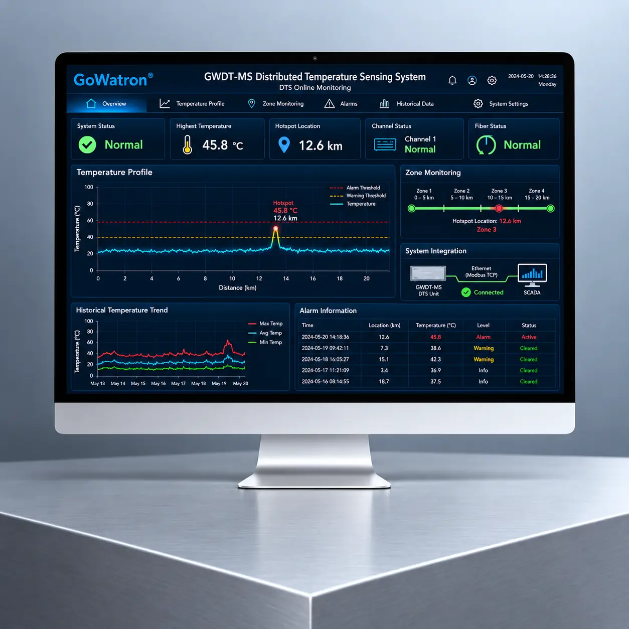
- The system outputs temperature data at the configured sampling interval and can display temperature trends along the fiber, maximum temperature, minimum temperature, zone average temperature and the locations of abnormal temperature rise events.
- “Continuous distributed temperature measurement” means that the entire sensing fiber participates in temperature sensing. However, the system output still consists of discrete sampling points. Actual event detection capability depends on the sampling interval, spatial resolution, signal-to-noise ratio and measurement update time.
Measurement Performance
The actual measurement performance of the GWDT-MS is mainly affected by the following factors:
- Measurement range
- Laser pulse width
- Fiber type and attenuation characteristics
- Fiber connectors, splice points and additional optical losses
- Spatial resolution
- Sampling interval
- Integration time
- Ambient temperature
- System calibration and differential attenuation compensation method
- Sensing cable installation method and thermal coupling conditions
- There are performance trade-offs among measurement range, spatial resolution, temperature resolution and measurement update time. In general, a longer measurement range or higher temperature resolution normally requires a longer signal integration time.
- Therefore, the minimum sampling interval, highest temperature accuracy, shortest update time and maximum measurement range stated in the technical specifications cannot necessarily be achieved simultaneously under the same system configuration and measurement conditions.
- Depending on the model and system configuration, the GWDT-MS supports either single-ended or double-ended measurement.
- In single-ended measurement, optical signals are launched and received from one end of the sensing fiber, resulting in a relatively simple system configuration. In double-ended measurement, both ends of the same sensing fiber are connected to the DTS interrogator or an optical channel-switching device. Data are acquired from both directions, helping reduce the effects of differential attenuation, localised bending loss, splice loss and connector loss on temperature measurement results.
Product Functions
Continuous Distributed Temperature Monitoring
- The system continuously acquires temperature data along the sensing fiber and generates a temperature-versus-distance profile. Depending on the interrogator, fiber type and measurement settings, the monitoring range of a single channel can extend from several kilometres to tens of kilometres.
Multi-Zone Management
- The sensing fiber can be divided into multiple independent monitoring zones according to the location, function and risk level of the monitored facility. Separate alarm thresholds, alarm logic, time delays and linked-control functions can be configured for each zone.
Multi-Level Temperature Alarms
Depending on the software version and system configuration, the following alarm types may be supported:
- Fixed-temperature alarm
- Temperature-difference alarm
- Rate-of-rise alarm
- Zone average temperature alarm
- High-temperature and high-high-temperature alarms
- Low-temperature or temperature-drop alarm
- Fiber-break or abnormal optical-loss alarm
- DTS interrogator and communication failure alarms
The simultaneous availability of these alarm types depends on the selected model, software functions and project technical agreement.
- Abnormal Temperature Location
- The system can identify localised hot spots, abrupt temperature-change zones or potential fire locations from the temperature profile and display the corresponding fiber distance.
- The system displays the optical distance along the sensing fiber. To correlate the fiber distance accurately with physical equipment, tunnel chainage, cable joints or pipeline locations, a mapping between fiber distance and the actual site location must be established during installation and commissioning.
- The detection and location accuracy of abnormal events depends on spatial resolution, sampling interval, measurement range, signal-to-noise ratio, integration time, fiber group refractive index, sensing cable installation and site calibration results.
Online Monitoring and Historical Analysis
The GWDT-MS supports continuous long-term operation. Depending on the monitoring software configuration, the following functions may be provided:
- Temperature profile display
- Multi-channel temperature monitoring
- Multi-zone operating-status display
- Maximum, minimum and average temperature statistics
- Historical temperature trend queries
- Alarm and event records
- Report generation and data export
- Electronic map, cable routing diagram or equipment layout display
- User access management
- System parameter configuration
Communication and System Integration
Depending on the model and project configuration, the GWDT-MS may provide:
- Ethernet interface
- RS-485 communication interface
- RS-232 maintenance or communication interface
- Digital inputs
- Digital outputs
- Relay alarm outputs
The system can optionally support Modbus TCP, Modbus RTU or other industrial communication protocols. It can exchange data and provide alarm integration or linked control with the following systems:
- Fire alarm system
- SCADA system
- Substation automation system
- Integrated cable condition monitoring system
- Building management system
- Tunnel integrated monitoring system
- Utility tunnel monitoring platform
- Customer-owned monitoring and data management platform
The actual communication interfaces, protocols, data-point list and linked-control logic shall be determined by the selected product model and project technical agreement.
Where the GWDT-MS is connected to a fire alarm system and performs fire detection, alarm transmission or linked-control functions, product selection, system design, certification scope and system integration shall comply with the applicable fire safety regulations, product certification requirements and acceptance requirements at the project location.
Fiber Condition Monitoring
- The system can monitor the backscattered signal, received optical power, abnormal optical losses and fiber-break conditions. When the sensing fiber breaks or significant additional optical loss occurs, the system estimates the fault location based on changes in the backscattered signal, facilitating inspection and repair by operation and maintenance personnel.
- This function is primarily intended to identify fiber breaks, connection faults and significant additional optical losses. It does not imply detection of all types of cable sheath damage, minor mechanical damage or structural changes that do not produce measurable optical loss.
System Self-Diagnostics
- Depending on the interrogator model, the system can monitor the laser source, optical receiver module, measurement channels, power supply unit (PSU) status, internal equipment temperature, storage status and communication status. An equipment fault alarm is generated when an abnormal condition is detected.
System Components
GWDT-MS DTS Interrogator
The GWDT-MS DTS interrogator is the core measurement and processing device and normally includes:
- Pulsed laser source
- Optical filtering and splitting module
- Photodetectors
- High-speed data acquisition module
- Signal-processing and temperature-demodulation module
- Communication and alarm-output module
- Power supply and equipment self-diagnostic module
The interrogator can be supplied in a 19-inch rack-mounted, wall-mounted or other industrial enclosure, depending on the product model and application.
Sensing Cable
The sensing cable serves as both the temperature-sensing element and the optical signal transmission medium. Conventional Raman-based DTS systems normally use multimode fiber, with common specifications including 50/125 μm and 62.5/125 μm. The selected fiber specification must match the optical system of the DTS interrogator.
Depending on the operating environment, the following sensing cable constructions may be selected:
- Metal-free flame-retardant sensing cable
- Metal-armoured sensing cable
- Fire-resistant sensing cable
- Corrosion-resistant sensing cable
- High-temperature-resistant sensing cable
- Low-temperature-resistant sensing cable
- Special-purpose sensing cable for specific industrial environments
The permissible operating temperature range of the sensing cable depends not only on the optical fiber itself, but also on the fiber coating, buffer, strength members, outer sheath, armour materials and installation method. This cable operating temperature range is distinct from the calibrated temperature measurement range of the complete DTS system.
The maximum permissible temperature of the sensing cable is not the same as the temperature measurement accuracy of the system, nor does it necessarily mean that the cable can operate continuously at that temperature. The continuous operating temperature and short-term withstand temperature must be confirmed separately.
Fiber-Optic Connection and Installation Accessories
The main accessories include:
- Fiber-optic patch cords
- Fiber-optic connectors
- Fiber termination boxes
- Fiber splice closures
- Splice protection accessories
- Cable fixing clamps
- Mounting brackets
- Optical channel-switching modules
FC/APC is one commonly used fiber-optic connector type. Other connector types may also be used depending on the equipment configuration. The connector type, fiber core diameter and connector end-face geometry must be compatible with the DTS interrogator and sensing cable.
Monitoring Software
The monitoring software is used for system configuration, temperature-data display, alarm management and historical data analysis. Its functions may include:
- Temperature profile display
- Multi-channel and multi-zone management
- Alarm threshold and alarm logic configuration
- Abnormal event location display
- Electronic map or cable routing diagram display
- Historical data queries
- Alarm and event records
- Report generation and data export
- User access management
- Third-party system communication configuration
Optional Supporting Equipment
Depending on project requirements, the following equipment may be provided:
- Industrial computer
- Data server
- Display monitor
- Uninterruptible power supply (UPS)
- Industrial Ethernet switch
- Audible and visual alarm device
- Digital I/O module
- Communication gateway or protocol converter
Main Technical Specifications
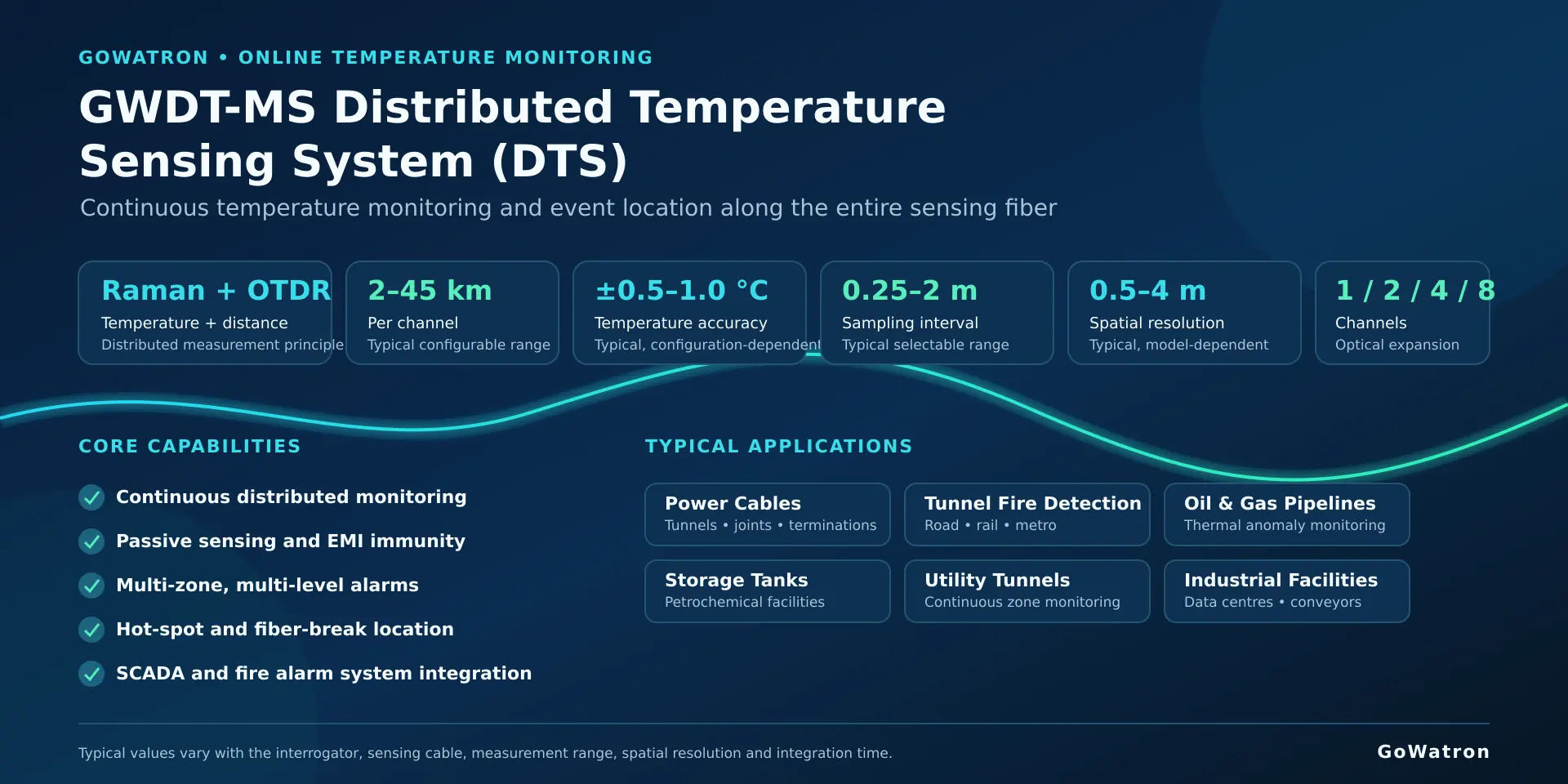
- The following values represent typical ranges available across different GWDT-MS models and configurations. The parameters are interdependent, and the best individual values shown in the table cannot necessarily be achieved simultaneously under the same configuration, measurement range and update time.
- Final supplied specifications shall be subject to the data sheet for the selected model, ordering configuration, factory test documentation and project technical agreement.
Sampling Interval
- The sampling interval is the distance along the fiber between two adjacent output temperature data points.
- A shorter sampling interval increases the number of output data points, but it does not mean that the system can resolve independent temperature events having the same physical length as the sampling interval.
Spatial Resolution
- Spatial resolution describes the system’s ability to distinguish adjacent temperature events or respond to localised temperature variations. It is mainly affected by the laser pulse width, receiver bandwidth, signal-processing algorithm and measurement range.
- Spatial resolution and sampling interval are different parameters and must not be used interchangeably. The sampling interval may be shorter than the spatial resolution, but the additional temperature data points produced are not fully independent of one another.
Temperature Accuracy
- Temperature accuracy is the maximum permissible deviation between the temperature measured by the system and the reference temperature under specified measurement-range, environmental, integration-time and calibration conditions.
- Temperature accuracy may vary with measurement distance, temperature range and environmental conditions. It shall therefore be stated together with the applicable test conditions.
Temperature Resolution
- Temperature resolution is the smallest temperature change that the system can reliably detect under specified measurement conditions and at a defined statistical confidence level.
- Temperature resolution indicates the system’s ability to detect small temperature variations and is not equivalent to temperature accuracy.
Distance Measurement Accuracy
- Distance measurement accuracy is the deviation between the fiber distance displayed by the system and the corresponding actual fiber length.
- This parameter is affected by the fiber group refractive index, installation slack, connectors, splice points, route bends, site calibration and the mapping relationship established for the monitored route.
- The fiber distance displayed by the system is not necessarily equal to the geographical distance, tunnel chainage or pipeline chainage. Correlation shall be established through on-site markers and distance mapping.
Applications
Power Cable Temperature Monitoring
- The system is suitable for high-voltage and extra-high-voltage power cables, cable tunnels, cable trenches, cable galleries, cable terminations and cable-joint areas. It continuously monitors cable surface temperature or the surrounding ambient temperature and identifies localised overheating and abnormal temperature rise events.
- The GWDT-MS directly measures the temperature at the location of the sensing cable; it does not directly measure the cable conductor temperature.
- Where cable conductor temperature or real-time current-carrying capacity must be estimated, the system should be combined with load-current measurements, environmental conditions, cable construction parameters, installation conditions and a suitable thermal model to provide real-time thermal rating (RTTR) or dynamic cable rating (DCR) functions.
Tunnel Fire Detection
- The system is suitable for road tunnels, railway tunnels, metro tunnels and underground passageways. Fixed-temperature, rate-of-rise and zone temperature-difference alarm logic can be used to identify abnormal temperature rises or potential fire locations.
- Where the system is used for statutory fire alarm, fire detection or fire protection system integration, the selected product model, sensing cable, monitoring software, alarm control equipment and system design shall comply with the applicable local fire codes, product certification requirements and acceptance requirements.
Oil and Gas Pipeline Leak Monitoring
- By monitoring localised heating, cooling or abnormal temperature changes along a pipeline, the system can provide supplementary information for identifying a possible leak and estimating its location.
- Detection performance depends on the transported medium, pipeline construction, thermal insulation, installation environment, leak size, sensing cable installation method and ambient temperature variations. The cable layout, detection algorithm and alarm thresholds shall be designed for the specific operating conditions.
- A temperature anomaly detected by DTS cannot, under all conditions, independently confirm that a leak has occurred. Where necessary, the DTS system should be used together with pressure, flow, acoustic or other leak-detection systems.
Storage Tanks and Petrochemical Facilities
- The system is suitable for temperature monitoring and early fire warning around tank perimeters, roofs and walls, as well as along process piping and within process plant areas.
- Although the sensing cable is a passive field element, the suitability of the DTS interrogator, fiber-optic connection equipment and complete system for use in potentially explosive atmospheres must still be determined according to hazardous-area classification, equipment location, intrinsic-safety design and applicable explosion-protection certification.
Utility Tunnels
- The system is suitable for continuous temperature monitoring in power compartments, telecommunications compartments and other utility zones. It can exchange data and provide alarm integration or linked control with an integrated utility tunnel monitoring platform or fire alarm system.
Conveyor Systems and Storage Facilities
- The system is suitable for mining conveyor belts, material-handling galleries, large warehouses and grain-storage facilities. It can be used to identify frictional heating, material self-heating and localised fire hazards.
- Specific alarm thresholds shall be determined according to normal operating temperatures, ambient temperature variations, equipment operating modes and site test results.
Hydraulic and Geotechnical Engineering
- When combined with active heating, thermal-tracer methods and specialist data analysis, the system can be used to assess seepage or leakage in dams, embankments, slopes and underground structures.
- Such applications normally require a dedicated design for the sensing cable layout, heating method, test procedure and data-analysis model. They cannot be implemented solely through conventional temperature alarm functions.
Data Centres and Industrial Facilities
- The system is suitable for temperature trend monitoring around power cables, busbar trunking systems, power distribution routes and industrial equipment in data centres and industrial facilities.
- For localised components such as busbar joints, cable joints and equipment connections, the sensing cable position, fixing method and thermal coupling arrangement shall be properly designed so that temperature changes in the sensing cable effectively represent the thermal condition of the monitored component.


