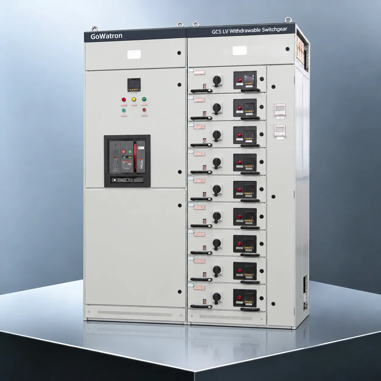
GCS Low-Voltage Withdrawable Switchgear
- The GoWatron GCS Low-Voltage Withdrawable Switchgear is a modular low-voltage switchgear and controlgear assembly designed for power distribution systems in power plants, oil and gas facilities, petrochemical plants, metallurgical facilities, textile mills, industrial plants, high-rise buildings and infrastructure projects.
- It is suitable for three-phase AC systems operating at 50/60 Hz, with a rated operational voltage of up to 690 V and main busbars rated up to 4,000 A. The switchgear can be used for receiving, converting, distributing and controlling electrical power, as well as for centralised motor control and reactive power compensation.
- For highly automated applications, the switchgear can be equipped with auxiliary contacts, measuring devices, communication interfaces and intelligent monitoring units according to project requirements. This configuration enables integration with power monitoring and automation systems.
- The GCS switchgear features a compartmentalised arrangement and withdrawable functional units. Its modular construction combines a compact footprint and flexible circuit configuration with ease of operation and straightforward maintenance. Each assembly can be customised according to the project single-line diagram, load characteristics and installation conditions.




1. Product Introduction
- The GoWatron GCS Low-Voltage Withdrawable Switchgear mainly comprises Power Centre (PC) sections for power distribution and Motor Control Centre (MCC) sections for motor control. Depending on project requirements, the assembly may include incomer panels, bus coupler panels, feeder panels, motor control panels, power factor correction panels and other functional panels.
- The switchgear may be designed, manufactured and verified in accordance with IEC 61439-1, IEC 61439-2, GB/T 7251.1 and GB/T 7251.12. The applicable standards, design verification, routine verification and project-specific testing requirements should be defined in the technical agreement.
- The main supporting structure may be assembled from 8MF open-section steel profiles or modular steel profiles with equivalent mechanical properties. Mounting holes are typically arranged on a 20 mm modular grid to facilitate component installation, circuit modification and future expansion.
- The enclosure is normally divided into a functional unit compartment, a busbar compartment and a cable compartment. Appropriate internal separation helps limit the effects of faults and improves safety during operation, inspection and maintenance. The form of internal separation depends on the project requirements and the verified product design.
- Withdrawable functional units may have connected, test, isolated and withdrawn positions, together with mechanical interlocks and position indicators. The interlocking system helps reduce the risk of incorrect operation, inadvertent closing or movement of a drawer under unsafe or improper operating conditions. The exact position definitions and interlocking logic depend on the drawer construction and selected switching devices.
2. Main Functions
- The GoWatron GCS Low-Voltage Withdrawable Switchgear is primarily used for receiving, distributing, controlling and protecting electrical power in low-voltage systems. Its principal functions include the following:
Power Distribution
- The switchgear can operate as a power centre for receiving and distributing low-voltage electrical power. Incomer, bus coupler and outgoing feeder circuits can be configured to supply motors, distribution boards and other low-voltage loads.
Centralised Motor Control
- When configured as a motor control centre, the switchgear provides centralised power distribution, control and protection for multiple motors.
- Depending on load requirements, each motor circuit can be equipped with circuit breakers, contactors, thermal overload relays, motor protection relays, soft starters or variable-frequency drives.
- The number of motor control or feeder circuits installed in one MCC panel depends on the drawer size, circuit current and dimensions of the selected components. In a typical high-density arrangement of small-capacity circuits, one MCC panel can accommodate up to 22 circuits. The actual number of circuits is subject to the final project design.
Electrical Protection
- Depending on the circuit application, the switchgear can provide short-circuit, overload, earth-fault, undervoltage, phase-failure and other protection functions.
- The available protection functions are determined by the selected circuit breakers, fuses, motor protection relays and intelligent monitoring units.
Reactive Power Compensation
- Fixed or automatically switched capacitor banks can be installed to improve the system power factor and reduce reactive current and distribution losses.
- The compensation capacity, number of switching stages and reactor configuration should be determined according to the load profile and harmonic conditions of the power system.
Measurement and Monitoring
- The switchgear can be equipped to measure current, voltage, frequency, active power, reactive power, power factor and energy.
- It can also monitor circuit-breaker positions, drawer positions, fault indications, alarms and other operating states.
Automation System Interfaces
- Withdrawable units can be equipped with auxiliary contacts, secondary disconnecting contacts, intelligent measuring and control devices and communication interfaces for the transmission of control commands, status indications, alarms and measurement data.
- The number of contacts and the communication configuration are determined according to the requirements of the project automation system.
- Optional communication protocols may include Modbus RTU, Modbus TCP and IEC 60870-5-104. Other protocols can be provided according to the selected intelligent devices and project requirements.
3. Product Construction
- The GoWatron GCS Low-Voltage Withdrawable Switchgear mainly consists of the following sections and components:
Supporting Structure
- The enclosure is of modular construction and may be assembled from 8MF open-section steel profiles or steel profiles with equivalent mechanical properties.
- The structure provides suitable mechanical strength, and mounting holes are arranged on a 20 mm modular grid to facilitate equipment installation, circuit modification and future expansion.
Functional Unit Compartment
- The functional unit compartment accommodates withdrawable feeder units, motor control units and other functional units.
- Drawer units may be available in 0.5-unit, 1-unit, 1.5-unit, 2-unit and 3-unit sizes. The actual dimensions and combinations depend on the verified enclosure design.
- The rated current of a withdrawable circuit is typically up to 400 A. Higher-current circuits may be arranged in fixed or plug-in configurations, or in another suitable form.
Busbar Compartment
- The busbar system consists of horizontal main busbars and vertical distribution busbars.
- Suitable separation is provided between the busbar, functional unit and cable compartments to meet the applicable requirements for clearances, creepage distances, temperature rise and short-circuit withstand capability.
- The busbar material, cross-sectional area, arrangement and supports are determined according to the rated current, short-circuit withstand capability, ambient temperature and project design.
Cable Compartment
- The cable compartment accommodates incoming and outgoing cables, terminal blocks, current transformers and other auxiliary components.
- The cable compartment width can be selected according to the number of circuits, cable entry configuration and cable dimensions.
- Typical cable compartment widths are 240 mm and 440 mm. Other widths may be provided according to project requirements. Top or bottom cable entry is available.
Withdrawable Units
- A withdrawable unit typically contains switching and protective devices, control components, primary disconnecting contacts, secondary disconnecting contacts, an operating mechanism and position indicators.
- Withdrawable units may have connected, test, isolated and withdrawn positions and are equipped with mechanical interlocks. The exact operating positions and interlocking logic depend on the product construction and selected switching devices.
Protective Earthing System
- The switchgear incorporates a continuous and reliable protective circuit, including a protective earth (PE) busbar. The enclosure frame, withdrawable units and other exposed conductive parts maintain reliable electrical continuity with the protective circuit.
- Hinged doors carrying electrical equipment are reliably bonded to the protective circuit by flexible protective conductors where required by the design. The protective earthing system is designed to meet the applicable requirements for protective-circuit continuity and fault-current-carrying capability.
4. Technical Parameters
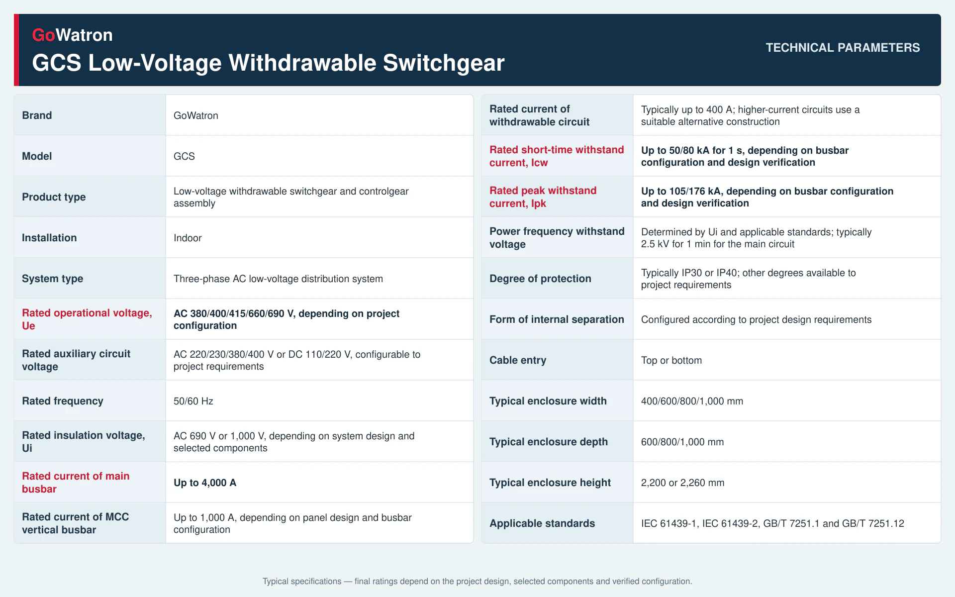
Note: The values above represent typical configuration ranges for GoWatron GCS Low-Voltage Withdrawable Switchgear. Final ratings, enclosure dimensions, degree of protection, form of internal separation and short-circuit withstand capability depend on the single-line diagram, component selection, the manufacturer’s design verification and the agreed project specifications.
5. Applications
The GoWatron GCS Low-Voltage Withdrawable Switchgear can be used in low-voltage power distribution and motor control systems in the following industries and facilities:
- Power plants: Power plant auxiliary power systems, auxiliary power distribution and motor control centres;
- Oil and gas facilities: Pumping stations, compressor stations and other low-voltage power distribution systems;
- Petrochemical plants: Process units, utility systems and motor control centres;
- Metallurgical facilities: Rolling mills, smelting plants, material handling systems and auxiliary production systems;
- Textile mills: Power distribution and centralised control of production equipment;
- Industrial manufacturing: Production lines, fans, pumps, compressors and other industrial loads;
- High-rise buildings: Power distribution for mechanical services, HVAC systems, water supply and drainage systems and public facilities;
- Water and wastewater facilities: Power distribution and control for pumps, fans and process equipment;
- Infrastructure: Low-voltage distribution systems for transportation facilities, data centres and public utilities.
The switchgear is particularly suitable for applications with a large number of circuits, a high degree of automation, centralised motor control requirements or integration with power monitoring and automation systems.
6. Normal Service Conditions
Installation location: Indoor;
- Maximum ambient air temperature: +40°C;
- Maximum average ambient air temperature over 24 hours: +35°C;
- Standard minimum ambient air temperature: −5°C;
- Special low-temperature configuration: Down to −15°C, subject to confirmation that the selected components are suitable for low-temperature operation;
- Installation altitude: Not exceeding 2,000 m above sea level;
- Relative humidity: Not exceeding 50% at +40°C; higher relative humidity may be permitted at lower temperatures;
- Atmospheric conditions: The ambient air should be free from concentrations of corrosive gases, conductive dust, salt mist or other contaminants that could seriously impair insulation performance;
- Installation conditions: The installation location should not be subject to severe vibration or impact exceeding the design limits of the product;
- Condensation: Occasional condensation caused by temperature variations should be considered. Anti-condensation heaters or dehumidification devices may be installed where necessary.
For installation at altitudes above 2,000 m, the insulation level, temperature rise, heat dissipation and current-carrying capability of the selected components should be evaluated according to the actual altitude. Enhanced insulation, improved ventilation or equipment derating should be applied where necessary.
If the ambient temperature, humidity, pollution level, vibration or other service conditions exceed the limits stated above, a project-specific assessment of the insulation performance, temperature-rise limits, component ratings, enclosure design and protective measures is required.


