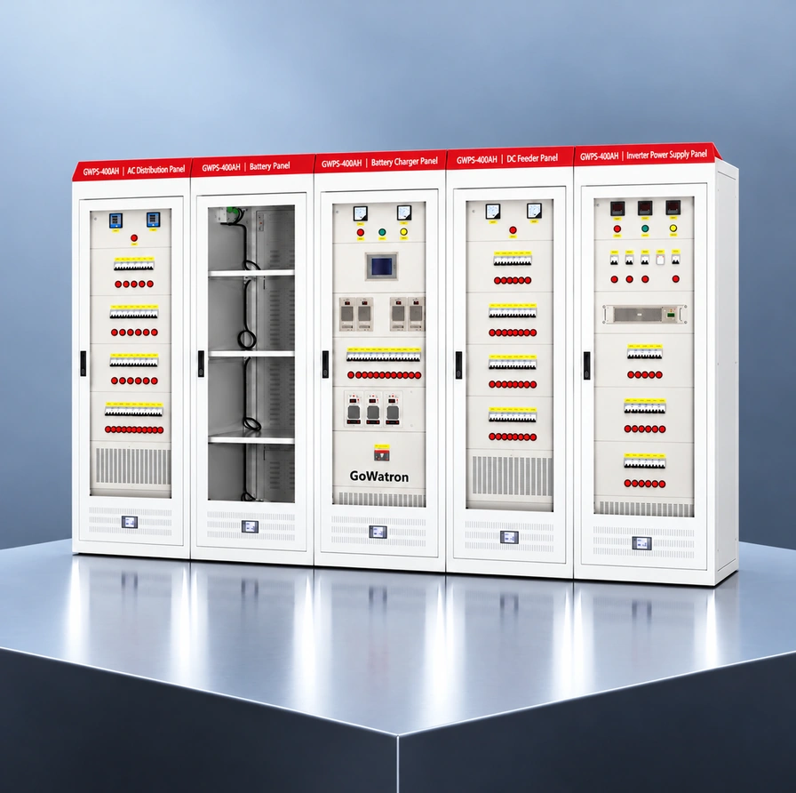
GWPS-110V/220V-400AH AC/DC Integrated Power Supply System / panel
- The GWPS-110V/220V-400AH AC/DC Integrated Power Supply System from GoWatron is designed for substations, power plants, industrial facilities and renewable energy step-up substations. Available in 110 V DC or 220 V DC configurations, it incorporates a battery bank rated at 400 Ah, together with AC distribution, high-frequency switching rectifiers, DC distribution, battery charging control, insulation monitoring, and central monitoring and control. Rectifier capacity is selected to meet load and charging requirements, while backup supply duration is calculated from the load profile and battery discharge characteristics.
- The system supplies DC power to protection relays, circuit-breaker tripping and closing circuits, substation automation equipment and DC emergency lighting. Following loss of the AC input, the battery bank continues to supply the DC loads. An optional inverter or uninterruptible power supply (UPS) can supply designated AC loads, and a DC/DC power supply can be provided for communication equipment.
- The system can be configured as a five- or six-cabinet arrangement, with individual cabinet dimensions of 2,260 × 800 × 600 mm (H × W × D). The arrangement includes battery charger, DC distribution and battery cabinets, with separate AC distribution or inverter cabinets where required. The final cabinet schedule depends on the system voltage, battery dimensions, number of outgoing feeders and selected equipment. A separate UPS cabinet is optional.





1. Model Designation
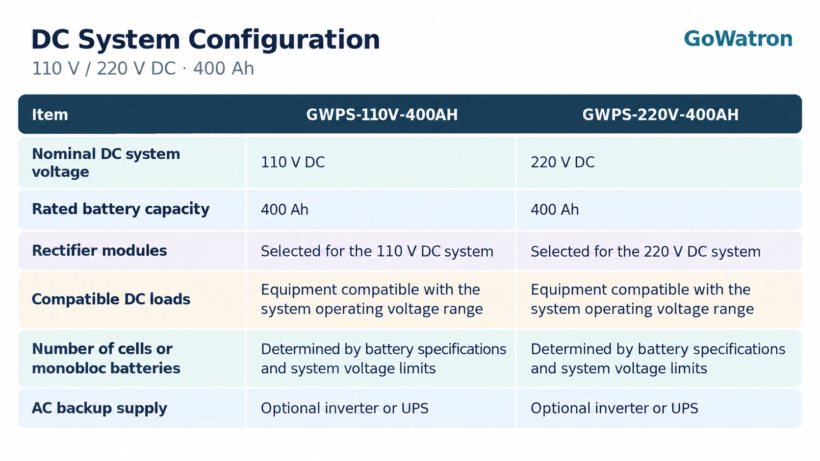
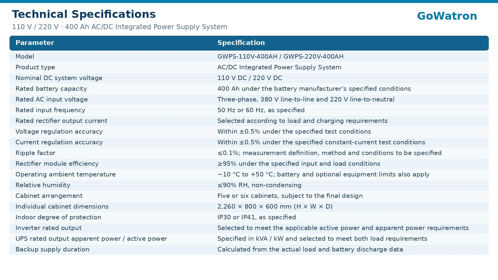
GWPS-110V/220V-400AH is the collective designation for the two voltage configurations. The individual ordering designations are GWPS-110V-400AH and GWPS-220V-400AH. The designation does not indicate simultaneous 110 V and 220 V DC outputs from one system.
The suffix 400AH identifies a rated battery capacity of 400 Ah. It does not specify rectifier output current, UPS rating or maximum load power.
2. Functional Modules
2.1 AC Distribution Unit
- The AC distribution unit receives power from station service transformers or other AC sources. Incoming protection, source transfer and distribution circuits supply the rectifier modules, auxiliary equipment and designated AC loads.
- A dual-source configuration can incorporate an automatic transfer switch (ATS) with appropriate interlocking. AC voltage monitoring and overvoltage, undervoltage and phase-loss alarms or protection are provided as specified.
- The unit may be integrated into the battery charger cabinet or installed in a separate AC distribution cabinet. ATS transfer alone does not provide an uninterrupted AC supply.
2.2 High-Frequency Switching Rectifier Modules
- The rectifier modules convert AC power into DC power to supply the DC loads and charge the battery bank.
- The modules operate in parallel and can be configured with N+1 redundancy. They support current sharing and output current limiting. Overvoltage, overtemperature and short-circuit protection are provided according to the selected module specifications. Hot-swap capability and procedures also depend on the selected modules.
- Total rectifier output current is selected to accommodate continuous DC loads, battery charging and any additional loads connected to the DC bus. Where N+1 redundancy is specified, the required output capacity must remain available with one module out of service.
2.3 DC Distribution Unit
- The DC distribution unit supplies protection, control, monitoring and DC emergency lighting loads through the DC bus and outgoing feeders.
- Feeders are equipped with circuit-breakers or fuses suitable for the applicable DC voltage and fault conditions. Switching-device status monitoring and alarms are provided as required. Protective devices are selected with consideration of prospective short-circuit current and protection coordination.
2.4 Central Monitoring and Control Unit
- The central monitoring and control unit acquires and displays AC input measurements, DC bus voltage, rectifier output current, battery bank voltage and current, switching-device status and alarms.
- A local human–machine interface (HMI) provides operating status displays, parameter settings and alarm access. Event recording and remote communication are available as configured.
- Charging control is matched to the selected battery type and includes, where applicable, float charging, equalising charging, charging current limiting and temperature compensation. Status and alarms from optional inverter or UPS equipment can be integrated where compatible interfaces are available.
2.5 Insulation Monitoring and Feeder Fault Location Unit
- For unearthed DC systems, the insulation monitoring unit monitors insulation resistance to earth and generates an alarm when the resistance falls below the configured threshold.
- With suitable feeder fault location equipment and sensors, the system can identify feeders with insulation faults and, where supported, indicate positive-pole or negative-pole insulation faults to earth. This assists maintenance personnel in locating earth faults.
2.6 Battery Monitoring Unit
- The battery monitoring unit measures battery bank voltage and charging and discharging current. Individual cell or monobloc battery voltage and temperature monitoring can be provided, together with abnormal-condition alarms.
- Internal resistance measurement is available as an option. The measurement method and interval depend on the selected equipment. Monitoring supports battery maintenance and fault investigation in conjunction with charging controls and protective circuits.
2.7 Inverter or UPS — Optional
- An inverter converts DC power into AC power for designated loads. Its output voltage, number of phases, power rating and transfer characteristics depend on the selected equipment.
- Where an uninterrupted AC supply is required, a suitable UPS or complete AC supply arrangement must be specified, including the necessary bypass, transfer, protection and monitoring functions. Equipment may be integrated into a multifunction cabinet or installed in a separate cabinet or rack.
- If the station battery bank supplies the inverter or UPS, compatibility with the equipment’s DC input voltage range must be verified throughout the specified charging and discharge range. AC load demand and conversion losses must be included in rectifier and battery sizing. A separate UPS battery bank, where used, is sized independently.
2.8 DC/DC Power Supply for Communication Equipment — Optional
- The DC/DC power supply converts the system DC voltage to the voltage required by communication equipment, such as 48 V DC.
- Output rating, isolation, earthing arrangement and redundancy are selected according to equipment and project requirements.
3. Cabinet Configuration and Dimensions
3.1 Cabinet Arrangement
The five- or six-cabinet arrangement comprises the following cabinet functions.
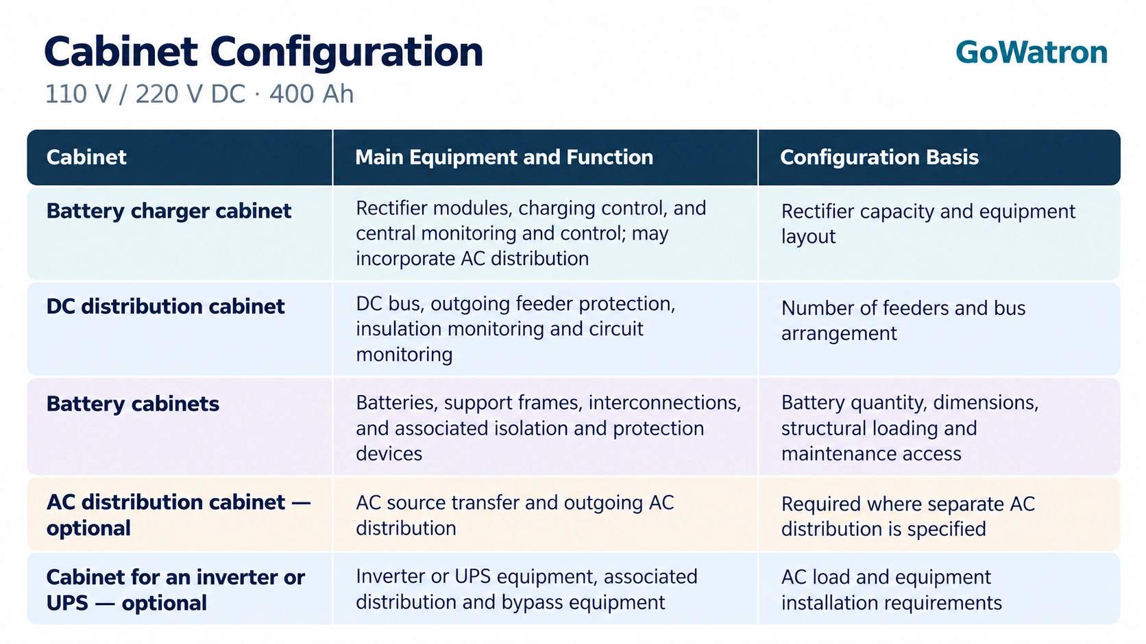
The choice between five and six cabinets depends on battery installation space and the need for separate functional cabinets. An additional cabinet may accommodate batteries, AC distribution or inverter equipment.
The final cabinet schedule and allocation of functions are determined by the project general arrangement drawing. The same number of battery cabinets must not be assumed for both voltage configurations.
Multiple battery cabinets may accommodate one battery bank. Cabinet quantity does not determine battery bank quantity or rated capacity. Additional cabinets may be required if separate UPS batteries or further functional units are specified.
3.2 Dimensions and Installation Requirements
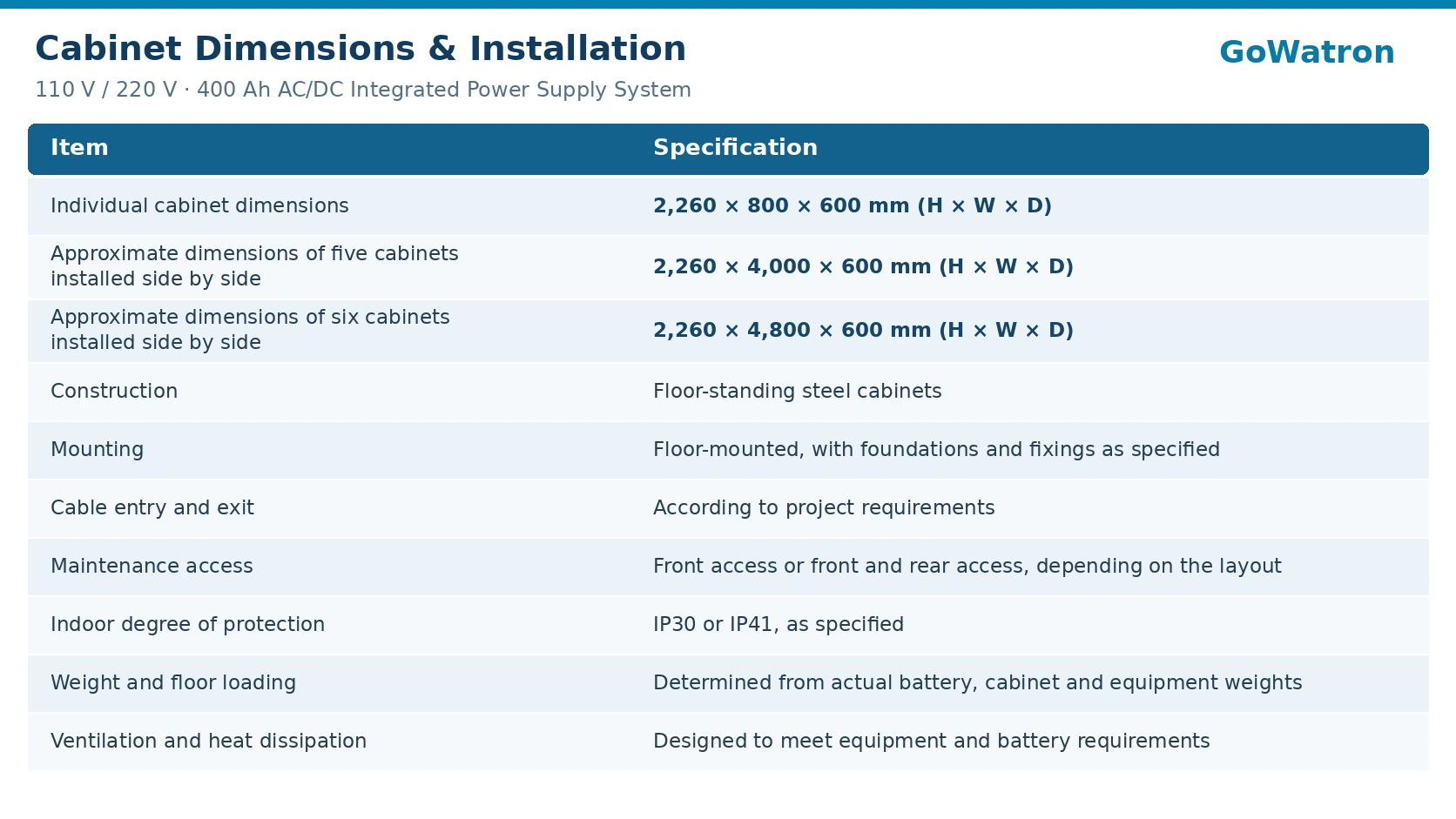
Overall dimensions assume equal-width cabinets and exclude gaps between cabinets, accessories, door-opening clearances and maintenance aisles. Cabinet dimensions or installation arrangements must be revised if selected equipment cannot be accommodated.
4. Battery Configuration and Load Sizing
The base configuration uses a 400 Ah valve-regulated lead-acid (VRLA) battery bank. The discharge rate, temperature and final discharge voltage associated with the rated capacity are specified by the battery manufacturer
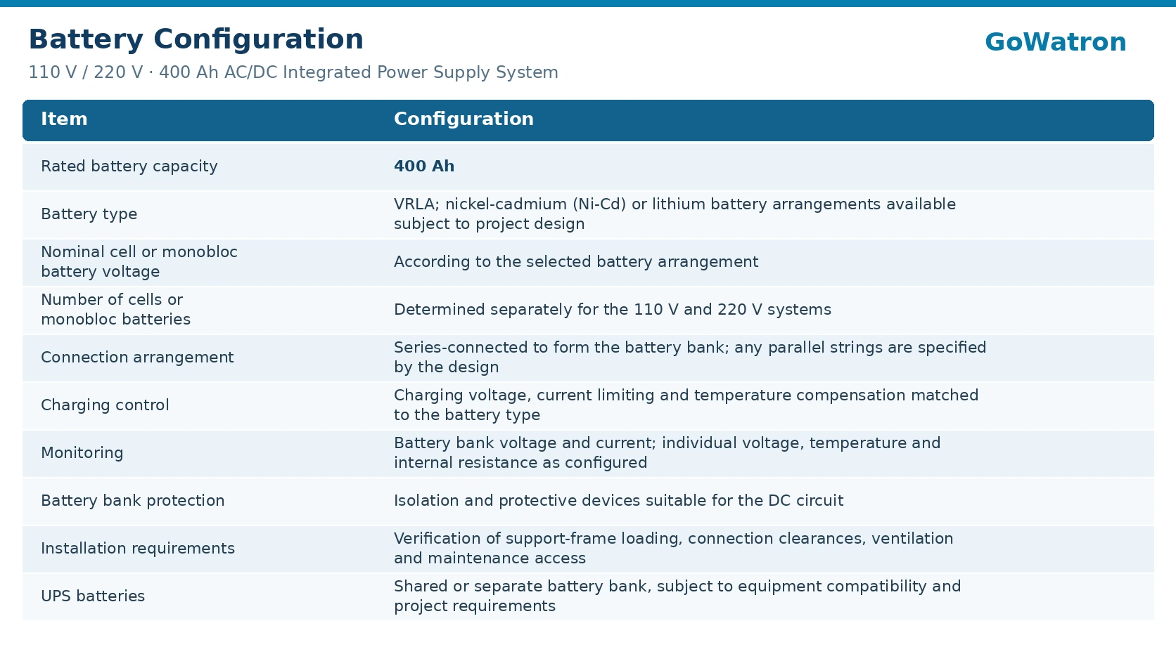
- Continuous DC Load Capacity is determined by the available rectifier output capacity after allowing for the required battery charging current. Where N+1 redundancy is specified, this capacity must also be verified with one rectifier module out of service.
- Backup Supply Duration is calculated using the load profile and battery discharge data. Sizing must account for continuous loads, short-duration loads such as circuit-breaker operation, voltage drop, temperature effects and battery ageing allowances.
- A rated capacity of 400 Ah does not establish a fixed maximum load power or backup supply duration. Battery connections and protective devices must also be suitable for the required continuous and short-duration currents.
- Alternative battery types require compatible charging, protection and monitoring arrangements. Lithium battery configurations require a suitable battery management system (BMS)..
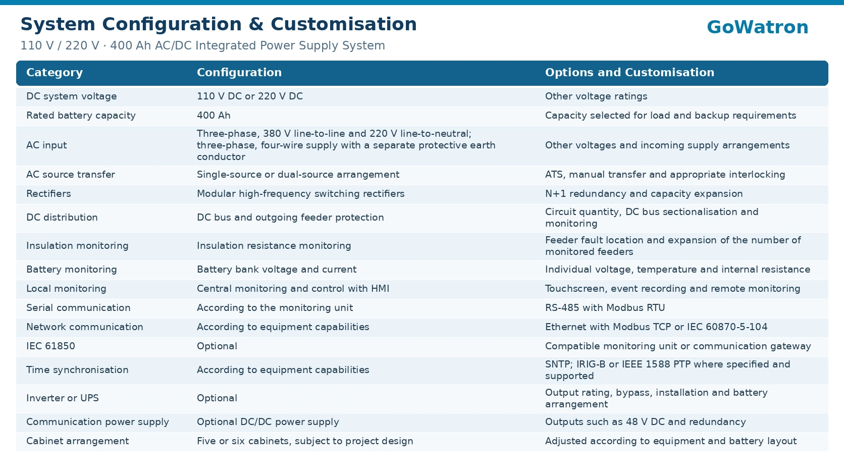
5. Configuration and Options
6. Technical Specifications
7. Typical Applications
7.1 Power Substations
- For secondary-system power supplies in 35 kV, 110 kV and 220 kV substations, supplying protection, control, substation automation and DC emergency lighting loads.
7.2 Power Plants and Renewable Energy Stations
- For thermal power plants, hydropower plants, utility-scale solar PV plants and wind farm step-up substations, supplying essential DC equipment and designated AC loads where optional AC backup equipment is provided.
7.3 Industrial Facilities
- For electrical distribution installations in petrochemical plants, metallurgical facilities, mines and other large industrial sites, supplying protection, control and monitoring systems.
7.4 Rail Transit and Other Infrastructure
- For secondary-system power supplies in traction substations and other infrastructure facilities. System voltage, capacity and backup supply duration are selected according to project requirements.7. Typical Applications


